Overview
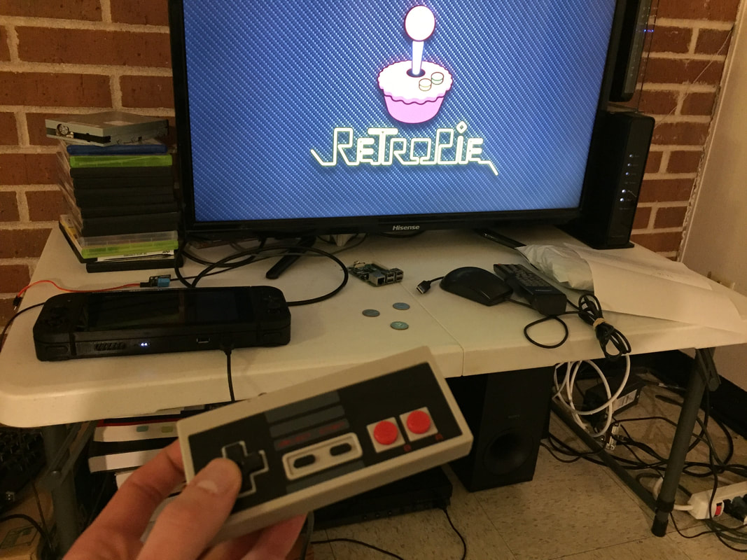
This page will go through the process of how I built my Retropie gaming console. I've broken it down into the three main sections of my build: The 3D Case, Hardware, and Software. Feel free to comment below any questions you have.
This page will go through the process of how I built my Retropie gaming console. I've broken it down into the three main sections of my build: The 3D Case, Hardware, and Software. Feel free to comment below any questions you have.
3D Case Model & Assembly
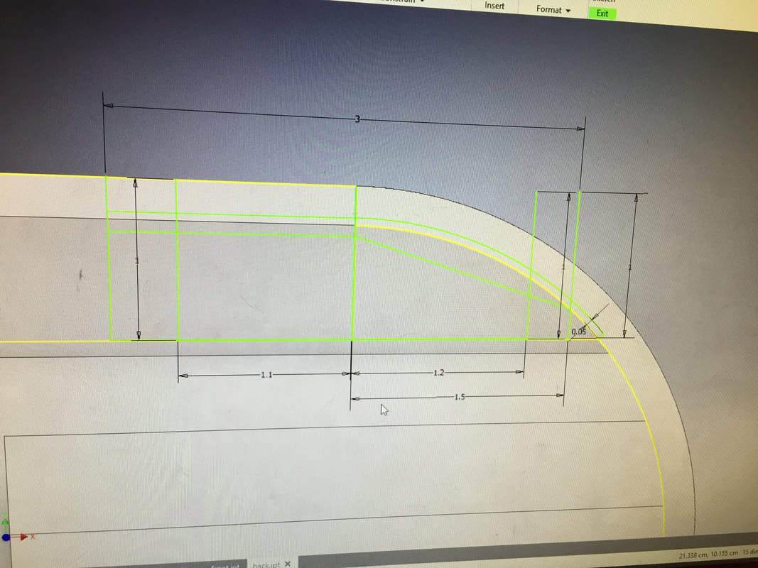
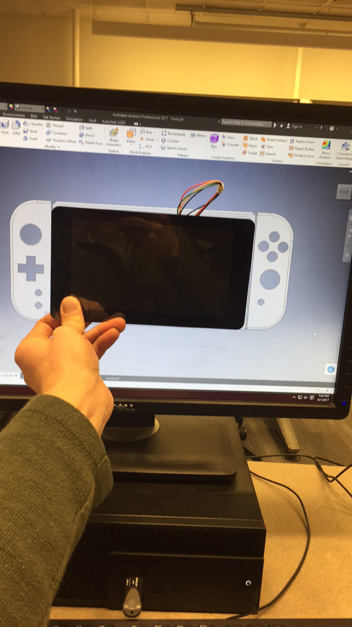
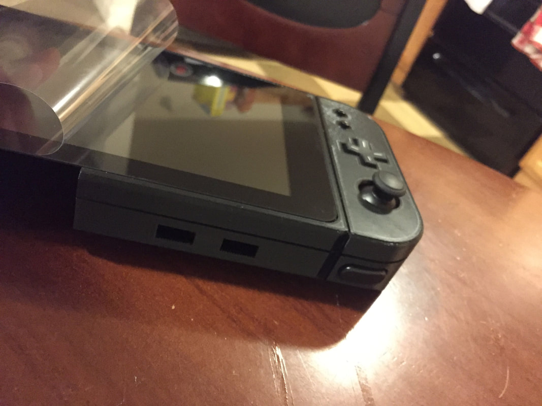
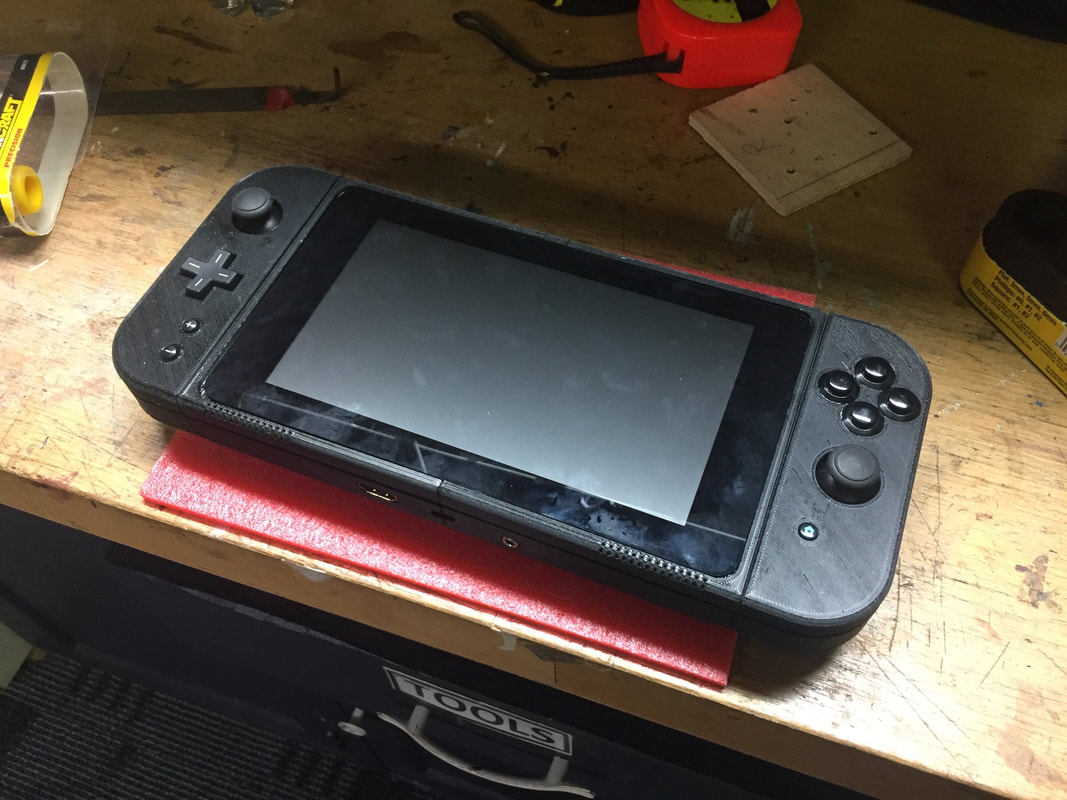
If you haven't realized it yet the Nintendo Switch was my inspiration for the design of the console. I focused on having the screen as the center of attention with controls on either side of it. To model my design I used Autodesk Inventor on a Windows machine and later switched to Autodesk Fusion to model on my Mac. I revised my design over the course of 4 months printing small sections to verify they would turn out correctly. Below shows the final design I went with the dimensions.
If you haven't realized it yet the Nintendo Switch was my inspiration for the design of the console. I focused on having the screen as the center of attention with controls on either side of it. To model my design I used Autodesk Inventor on a Windows machine and later switched to Autodesk Fusion to model on my Mac. I revised my design over the course of 4 months printing small sections to verify they would turn out correctly. Below shows the final design I went with the dimensions.
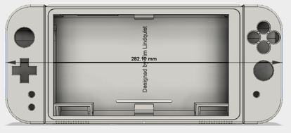
Width: 282.10mm
|
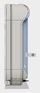
Thickness: 35.40mm
|
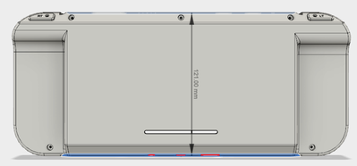
Height: 121.00mm
|
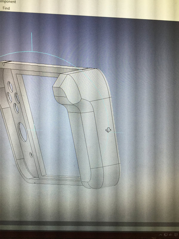
The 7-inch touch screen set the constraint on how big the middle section was and the left and right control pads were scaled appropriately to match the sizing. The case needed a required thickness of 35mm to house the 10,000 mAh batteries. This resulted in the device being drastically thickened and looking like a brick. To combat this, the handhold areas were relieved of thickness to create the illusion that the device is thinner than it actually is. The top and bottom of the device chamfer backward so it appears to end sooner than it does. This made the device easier to hold and improved the physical appearance.
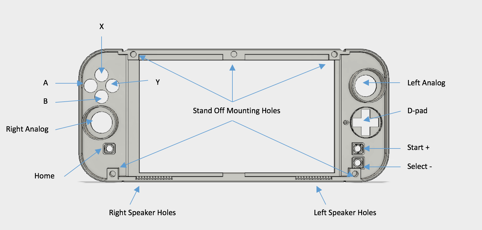
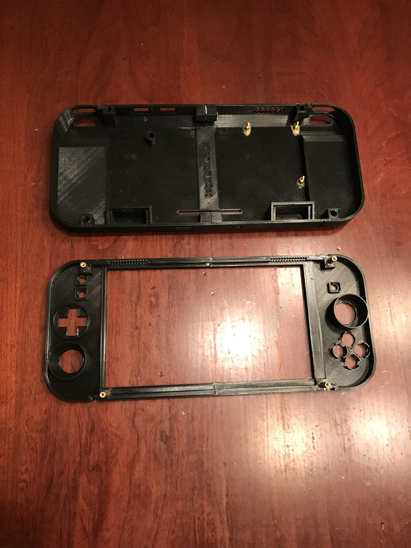
Front: The face plate contains all the mounting holes for the buttons and joysticks. The large hole in the center is for the screen to fit in. The standoff mounting holes will have standoff metal segments glued in to be used for alignment and lock with the back plate.
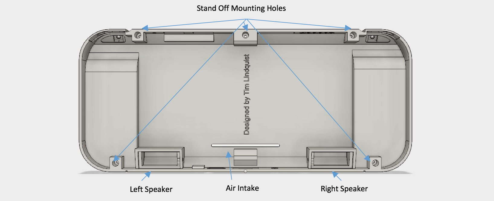
Back: The backplate contains two resonation chambers for the speakers to be placed. These are directed towards the holes on the front plate to increase sound permeability. The standoff mounting holes on the back plate are used as alignment holes for the front pegs to slide into.
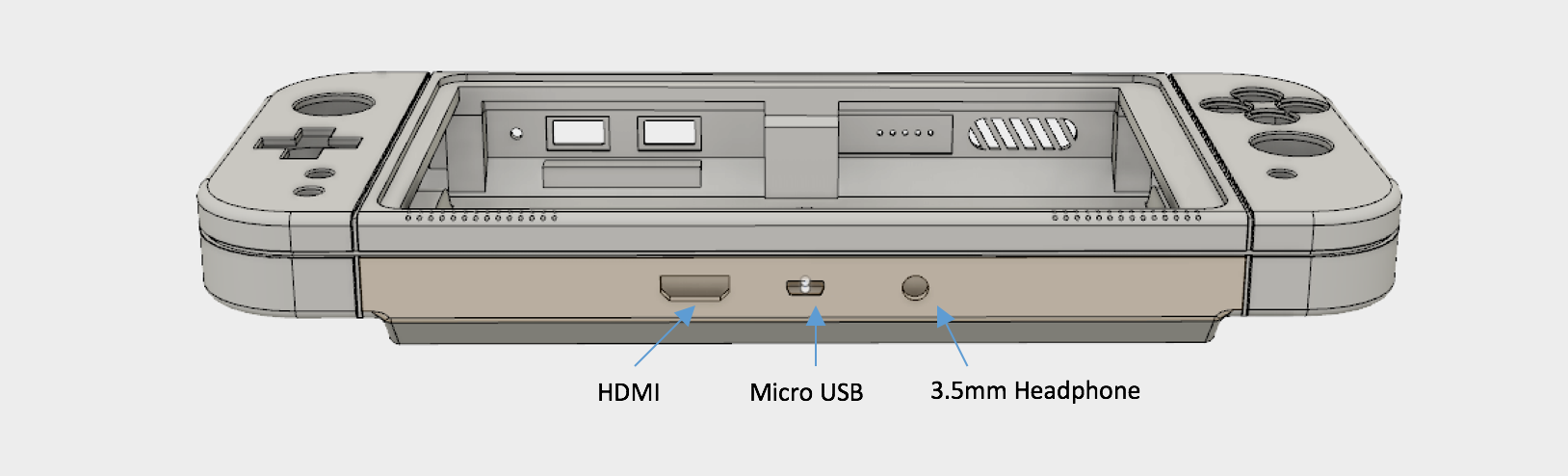
Bottom: Underneath the device are three I/O ports. HDMI out to forward contents to another display. Micro USB for charging the device. 3.5mm headphone jack to listen with earbuds.
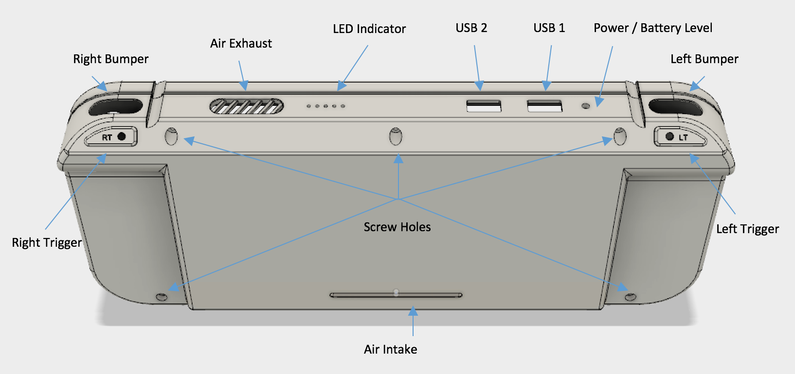
Top: Above we have some more user input buttons in the form of Bumpers and Triggers. Air flow for cooling is drawn in through the intake located on the back of the device and flows past heat sinks into a duct system to be exited out of the exhaust on top. Right of that is the 5 LED indicator which is a multi-use identification system. After that There are 2 USB type-A ports for serial interfacing. The Power button is used for turning ON/OFF the device (hold) and for displaying battery percentage (press). Screw holes secure the inserted metal stand off pegs to join the front and back plates.
|
Printing:
To print the device download my 3D model files and send them to your 3D printer. The printer I used was a Prusa i3 Mk2 along with black plastic filament. Printing quality was found to be best in a medium resolution setting. Be sure to add structural material under in the device (Hand holds will look poor without it). Back pieces were printed with the back flush with the platter. Front pieces were printed with the front face flush with the platter. If I were to print another case I would want to use a new color such as atomic purple to show off the internals. If you're like me and have an 8inch printing bed to work with you will need to print the 4 piece version which will be assembled after printing. However, if your bed is large enough to do as a single piece, print the front and back plate as a single unit and avoid the pain of piecing them together. |
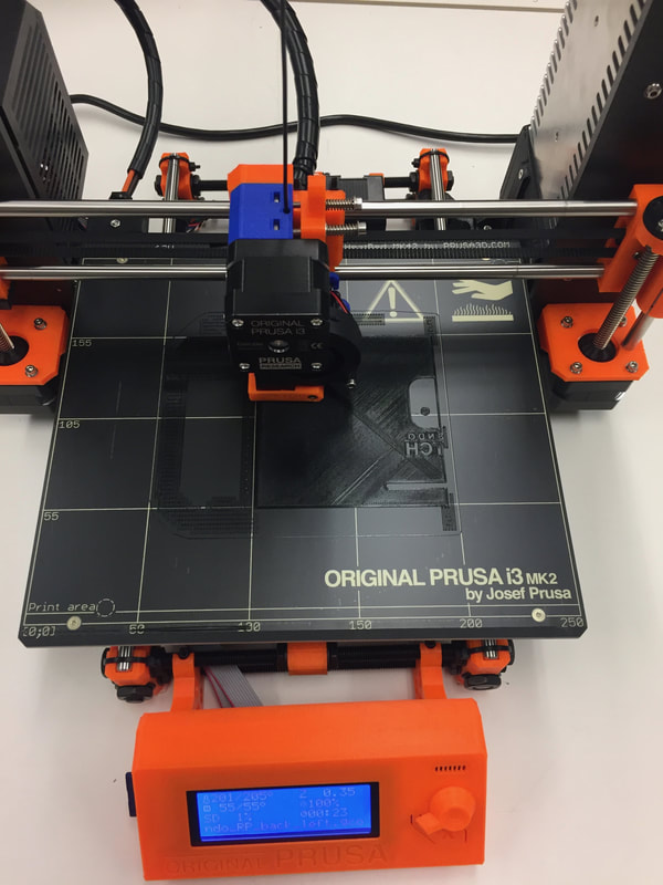
Prusa i3 Mk2
|
Assembly:
To assemble first join the front right and left pieces by inserting a metal dowel into the alignment holes. Next place superglue on the joints and secure the halves together. Repeat the process for the bottom right and left halves. After this, you should be left with an assembled front and back half. Now it is time to attach the 5 metal standoffs for merging the front and back plates. The easiest way to do this is to first get the standoffs to the correct length. 13 mm depth in back 5 mm depth in the front. So make the standoffs 18mm or slightly less. I did this by placing a longer standoff in a vice grip and using a grinder to shave down the size. Be sure to only grind off one side because you will need the threads on the other. After you get the correct length glue all the ground off sides to the front face using regular gorilla glue and let it dry. Be sure they are all standing up straight during this process. Once dry scrape the excellent glue that foamed up so that the faces can be flush when put together. Now see if you can insert the back plate onto the standoffs to join with the front. Screw together through the back plate to secure. Glue screen on by lining the frame with the duel tube Gorilla Epoxy. I put too much on when I did this and it overflowed onto the screen. Luckily it rubs off! Clamp and let dry for a while then line the backside with regular Gorilla glue.
**Note: Try not to get thin CA glue (super glue) on the exterior as it will "burn" the PLA and stain a white color.

Hardware
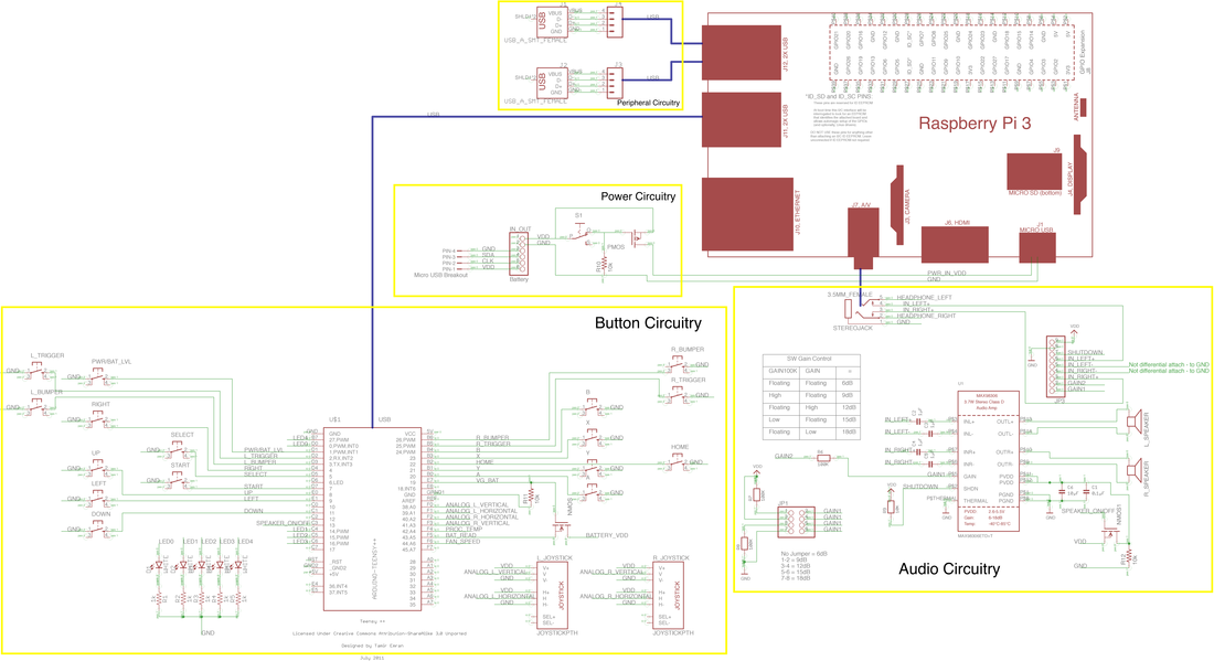
Here is a circuit schematic I made showing in detail how the whole system is wired.
Here is a circuit schematic I made showing in detail how the whole system is wired.
Nintimdo RP Wiring
Button Circuitry:
Capturing all the button presses is done using a Teensy ++ 2.0.
Capturing all the button presses is done using a Teensy ++ 2.0.
Digital pins on the microcontroller are used for any binary press buttons. The analog pins are used for buttons that have multiple states such as the joysticks. To wire the digital pins simple wire the digital pin to the switch, have the other end of the switch wired to ground. When the button is pressed it will pull the high voltage pin down for the controller to sense. You do not need to worry about resistors as they are included on the Teensy board. To wire the analog pins you will need to bias your analog device with a high and low voltage and read a voltage level within that range on the analog pin. For the joysticks, there are 3 inputs for each axis. Supply a 5V to one of the pins, GND to another and the voltage read line to the last. Be sure to hook this up correctly or it will not work (use a multimeter to see if the output voltage changes on the correct pin.) Essentially the joystick is a variable resistor that works like a voltage divider. The output voltage on the read pin will vary between 0 and 5V depending on the joystick's position. (Usually, the bias 5V and GND are on the outer input pins of the joystick and the middle one will be your variable voltage read pin. If 5V and GND are different than mine your controls will be inverted, this can be fixed in software or rewiring).
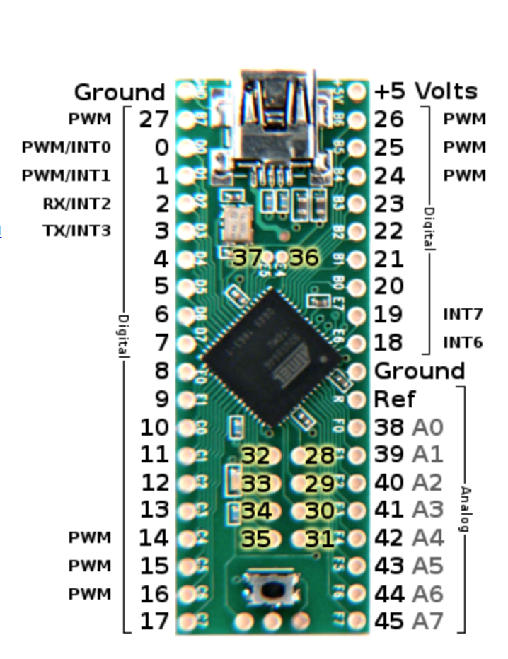
Teensy ++ 2.0 Pinout
|
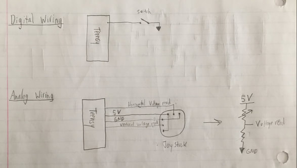
Digital & Analog Wiring
|
|
Power Circuitry:
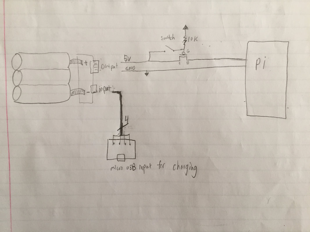
The three cell Anker battery supplies power to the entire device. To turn the device on/off, the output of the battery regulator is wired to a switch and then to the Raspberry Pi. Because the device can draw up to 2A a simple 250mA toggle switch cannot handle the current requirement. Instead, you can use the switch to control the gate voltage on a PMOS transistor to serve the purpose of a switch. Wire the 5V of the battery to the source of a PMOS transistor and the switch. The other end of the switch is wired to the gate of the PMOS transistor and to a 10K resistor connected to GND (when the switch is open to prevent the gate from floating it ties it to GND through a resistor). The Drain is wired to the 5V input on the Raspberry Pi along with the ground. To charge the battery simply wire the micro USB female breakout board to the correct charging pins (extends input to the case). I hid this switch in the air intake in the back of the device. Originally I was planning to instead have the battery button turn the device on and off by holding it for a certain duration, unfortunately, I ran out of space and had to do the simple implementation. This alternative design is shown in the schematic below. 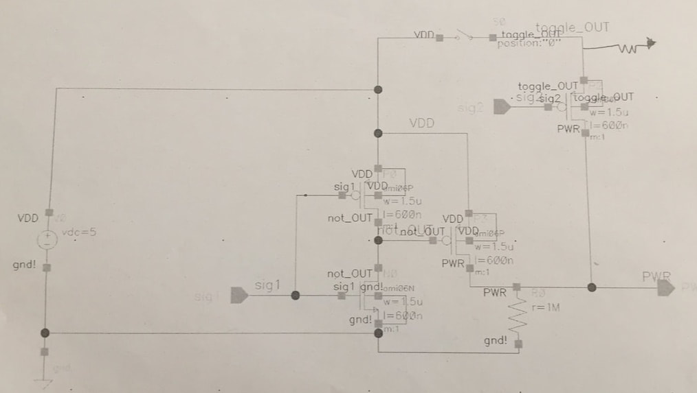
Alternative Design Schematic
|
Power Circuitry
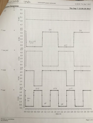
Alternative Design Transient Response
|
Alternative Power Circuitry Design:
(If you are a beginner, I recommend using the easier circuit described in the Power Circuitry section)
The purpose of this alternative circuit is to utilize the battery push button to turn the device on and off. (Hold for x seconds= ON/OFF, single press=battery level read). This alternative design I came up with has only been tested in simulation. If I had room I would have made a small PCB with surface mount NMOS and PMOS transistors to implement it. The alternative design is comprised of an inverter, two PMOS pull up transistors, a push button (the battery read button) and resistors to make sure no floating occurs. Sig 1 is the input signal to the gates of the inverter. Sig 2 is the input to the PMOS following the push button. NOT_out is the output signal of the inverter fed into the gate of the last PMOS. Sig 1 and Sig 2 are generated digital signals from the teensy and are grounded when the device is off. PWR is the input power to the Pi. The Pi powers up the teensy via the USB.
The device is off: Sig 1 & sig 2 are grounded because teensy is off. This results in NOT_out=5V from the inverter and the PMOS following the push button to turn on (won't do anything since the switch is open). The second PMOS following the inverter is receiving 5V at the Gate so it is off. The PWR is connected to GND through a resistor, because of this no current is flowing, resulting in the Pi being OFF.
The push button is held to turn on the device: When this happens 5V runs through the switch and through the push button PMOS to be connected to PWR. PWR can now boot up the Pi which powers up the teensy. You need to program the teensy to set a digital Pin HIGH that is connected to sig 1, this will hold the state for you and make sure the device stays on. It holds the state by sending 5V to sig 1 (into the inverter) which makes NOT_out=0V going into a PMOS gate to turn it on and directly connect 5V to PWR. Once this is completed you can have the Teensy set another digital Pin HIGH that is connected to sig 2 for the push button PMOS gate. By setting sig 2 to a high voltage you turn off that transistor isolating any button push from now on to not affect the power. This sequence allows a push button hold to turn on the device. If you don't hold down long enough for the Teensy to change sig 1 to HIGH the device will prematurely shut down.
The device is now on: Since the device is now on if you have a digital sense line to the resistor following the push button you can find out when the button is being pressed. Pressed=5V released=0V. Depending on how long you see 5V=HIGH you can program the teensy to either give you a battery level reading or if it's held for X seconds to turn off the device.
Want to turn off the device: You have two options in this part. You can write code for the teensy to sense when the buttons been held long enough and then set the Sig 1 and sig 2 pins LOW to kill itself. A potential issue of this is a hard shutdown may cause data corruption in the pi. Instead, you could have the teensy send a command to the Pi via serial that is interpreted by the trigger-happy Daemon to send the power down command to the pi. I worry about the teensy loosing power mid shutdown of the pi and performing a hard shutdown again! You will have to test to discover when power is lost to the USB devices during the shutdown sequence. (a capacitor may solve the problem if there is one on between 5V in GND on the USB output to keep the teensy on a bit longer.)
This alternative implementation may not work as I envisioned since I have only tested in simulation but I hope this provides a better understanding for you on what I was trying to implement.
Audio Circuitry:
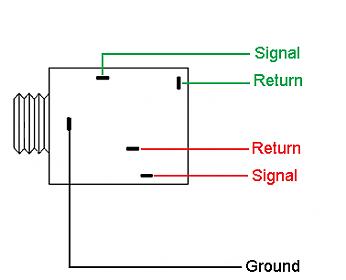
For the audio I wanted the sound to naturally play out of the speakers (if not muted) and redirect into headphones if they are plugged in. Fortunately, many of the female 3.5mm headphone jacks are mechanically capable of doing this. When a male plug is inserted the speaker leads will bend and create an open circuit, thus preventing the signal from reaching the speakers. Since the speakers are a larger load the audio signal must be amplified to be able to hear it. This is done using a stereo class D amplifier I found on Adafruit. Simply bias the amplifier with 5V and GND. We do not have differential audio inputs so wire the left and right speakers to the positive terminals and tie the negative terminals to GND. Gain is adjusted using the jumper. I set the gain to the maximum and am changing the output audio signals amplitude via software to adjust volume. To mute the device I have an NMOS transistor controlling the 5V bias. This NMOS transistors gate is controlled by the Teensy. An issue I have is a constant high-frequency noise is present in the external speakers. I will analyze this on an oscilloscope, may be coming from the 5V bias because of some regulator switching at the battery or the lines may be picking up RF somewhere. Also, be sure to twist the right and left lines to minimize electromagnetic interference (EMI).
For the audio I wanted the sound to naturally play out of the speakers (if not muted) and redirect into headphones if they are plugged in. Fortunately, many of the female 3.5mm headphone jacks are mechanically capable of doing this. When a male plug is inserted the speaker leads will bend and create an open circuit, thus preventing the signal from reaching the speakers. Since the speakers are a larger load the audio signal must be amplified to be able to hear it. This is done using a stereo class D amplifier I found on Adafruit. Simply bias the amplifier with 5V and GND. We do not have differential audio inputs so wire the left and right speakers to the positive terminals and tie the negative terminals to GND. Gain is adjusted using the jumper. I set the gain to the maximum and am changing the output audio signals amplitude via software to adjust volume. To mute the device I have an NMOS transistor controlling the 5V bias. This NMOS transistors gate is controlled by the Teensy. An issue I have is a constant high-frequency noise is present in the external speakers. I will analyze this on an oscilloscope, may be coming from the 5V bias because of some regulator switching at the battery or the lines may be picking up RF somewhere. Also, be sure to twist the right and left lines to minimize electromagnetic interference (EMI).
3.5mm Female Headphone Jack
|
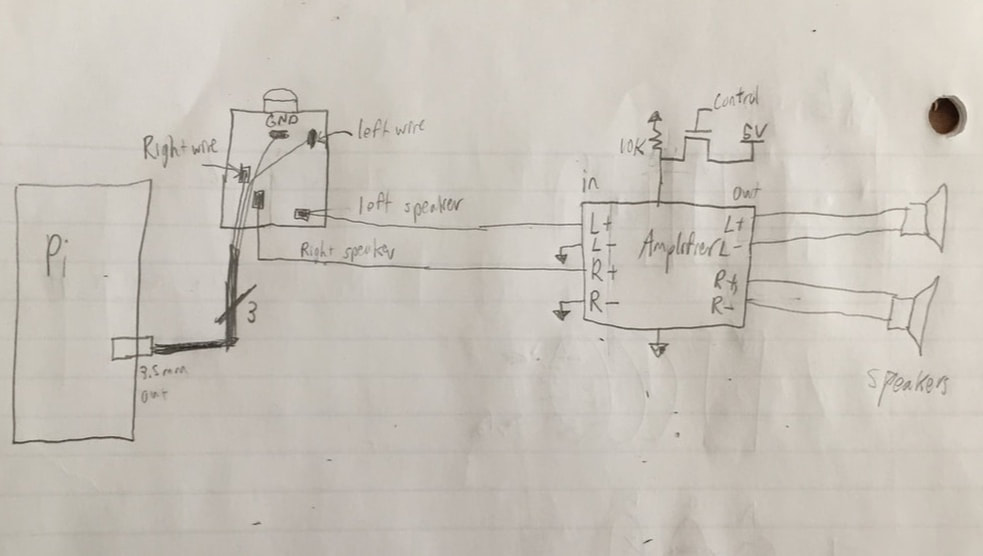
Audio Wiring
|
|
Peripheral Circuitry:
This circuitry includes the USB mounts and LED indicator. Order the PCB in my link and cut in half along the dotted line using a bandsaw. On the USB side, all solder the two female USB ports onto the board. On the LED side solder the 5 LED's and 5 resistors in series. 5V, GND, D-, D+ can be extended using wires from the Raspberry PI's desoldered USB's to the PCB. The LED PCB can be placed so that the light shines through the holes on top of the case. Wire 5 PWM outputs of the Teensy to the LED's along with GND. By varying the duty cycle you can alter the brightness of the LED's. |
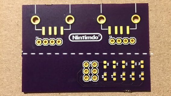
USB and LED PCB
|
Buttons:
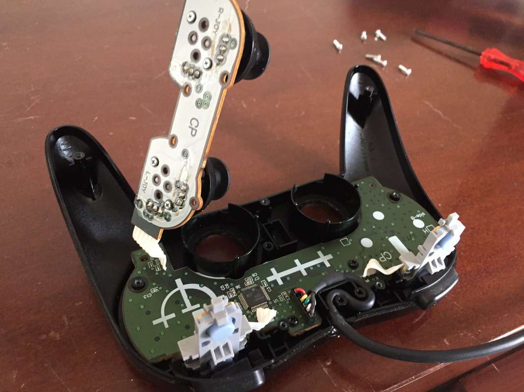
The analog sticks, start, select, home, right/left bumpers, D-pad were stripped from a used Wii Classic controller I found online. Since I didn't have a precise enough housing I couldn't use the silicone bounce pads with a sortable PCB behind to register a button push. Instead, I stuck tactile buttons behind each of the plastic button faces. These tactile buttons were soldered onto a mounted perf board behind the front panel. Everything was put together using super glue for an initial hold then secured using regular Gorilla glue. Since the A, B, X, Y buttons were often used I wanted to get something that could be pressed deeper so I bought some panel mount buttons. These are stiff when you get them but are working fine now that I've broken them in.
The analog sticks, start, select, home, right/left bumpers, D-pad were stripped from a used Wii Classic controller I found online. Since I didn't have a precise enough housing I couldn't use the silicone bounce pads with a sortable PCB behind to register a button push. Instead, I stuck tactile buttons behind each of the plastic button faces. These tactile buttons were soldered onto a mounted perf board behind the front panel. Everything was put together using super glue for an initial hold then secured using regular Gorilla glue. Since the A, B, X, Y buttons were often used I wanted to get something that could be pressed deeper so I bought some panel mount buttons. These are stiff when you get them but are working fine now that I've broken them in.
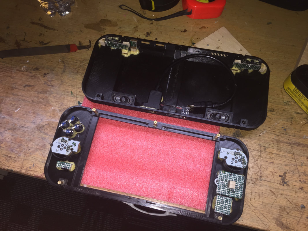
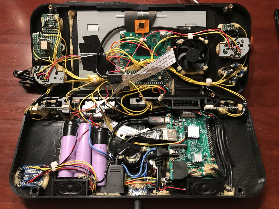
Fully Wired Internals
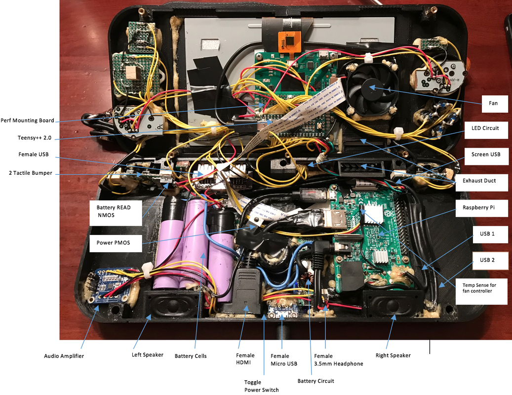
Internals Labeled
Software
Teensy:
If you wired it exactly the same as me you can just use the code I provided on Github. However, I would recommend writing it yourself as you will understand the system better and be able to easily manipulate and customize it to your liking. Programming is very simple, it really comes down to writing a bunch of if statements to check if your buttons were pressed. A helpful instruction set from PJRC. You can use the Arduino IDE to write your code in as well as upload to Teensy.
Digital Buttons:
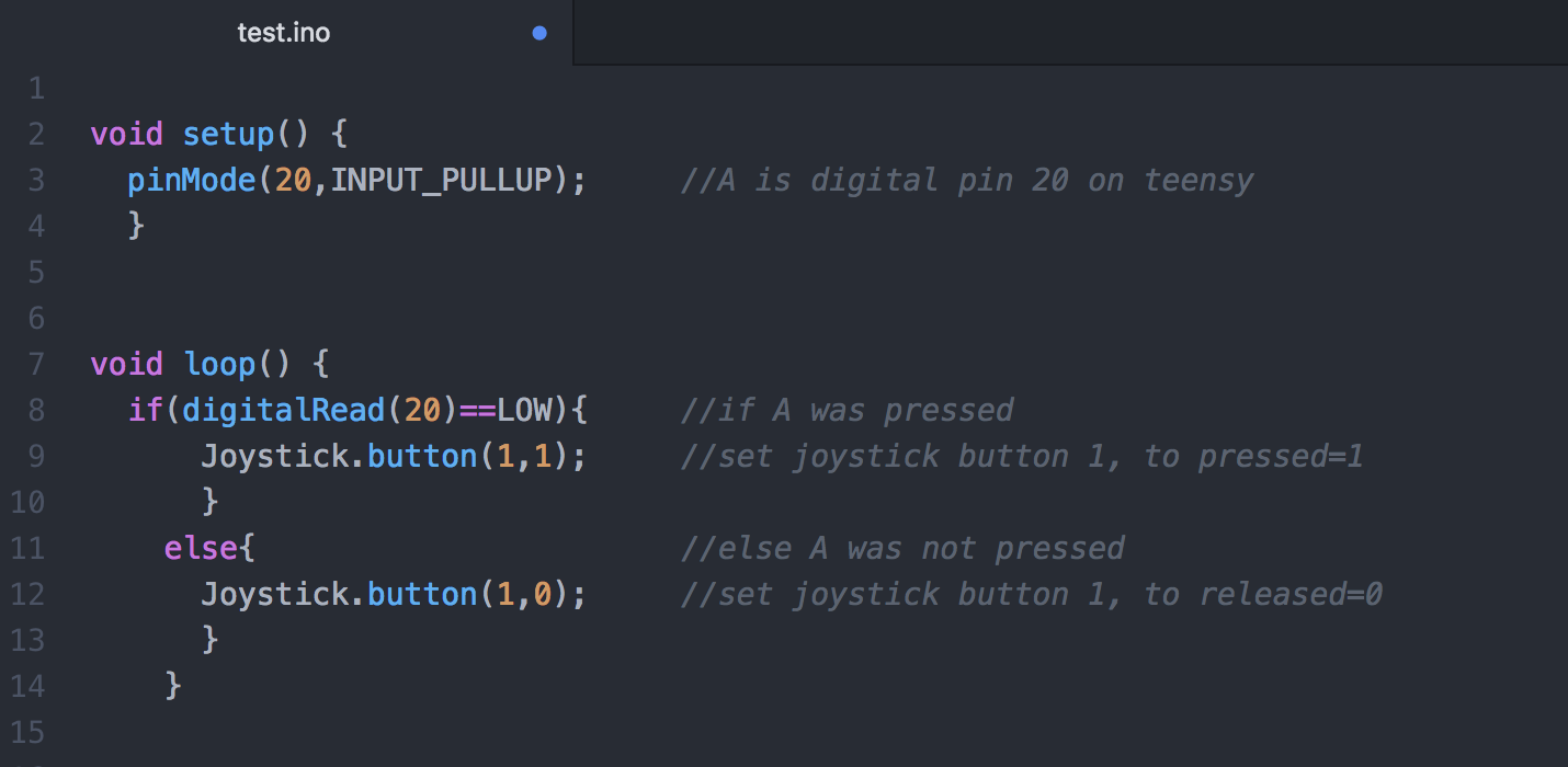
This example shows me checking to see if digital pin 20 was pressed and then outputting the correct serial joystick command. You can choose any 1 through 32 for the button since Retropie does a controller mapping setup at the beginning anyways. Joystick.button(buttons: 1-32, Pressed=1 Released=0)
This example shows me checking to see if digital pin 20 was pressed and then outputting the correct serial joystick command. You can choose any 1 through 32 for the button since Retropie does a controller mapping setup at the beginning anyways. Joystick.button(buttons: 1-32, Pressed=1 Released=0)
Digital Program Example
Analog Buttons:
In the example below, the right joystick vertical is wired to analog pin 41. The analogRead(pin) function receives a voltage level between 0 and 5V and returns a value of 0 to 1023. An ideal center position would correspond to 2.5V or 512, however this was not the case for my analog stick so adjustment needed to be made. This was done through a remapping shown below. After that I needed to check if the bounds were not exceeded 0 to 1023. Lastly the analog joystick command was sent over serial to be the analog button Z using Joystick.Z(value 0 to 1023).
In the example below, the right joystick vertical is wired to analog pin 41. The analogRead(pin) function receives a voltage level between 0 and 5V and returns a value of 0 to 1023. An ideal center position would correspond to 2.5V or 512, however this was not the case for my analog stick so adjustment needed to be made. This was done through a remapping shown below. After that I needed to check if the bounds were not exceeded 0 to 1023. Lastly the analog joystick command was sent over serial to be the analog button Z using Joystick.Z(value 0 to 1023).
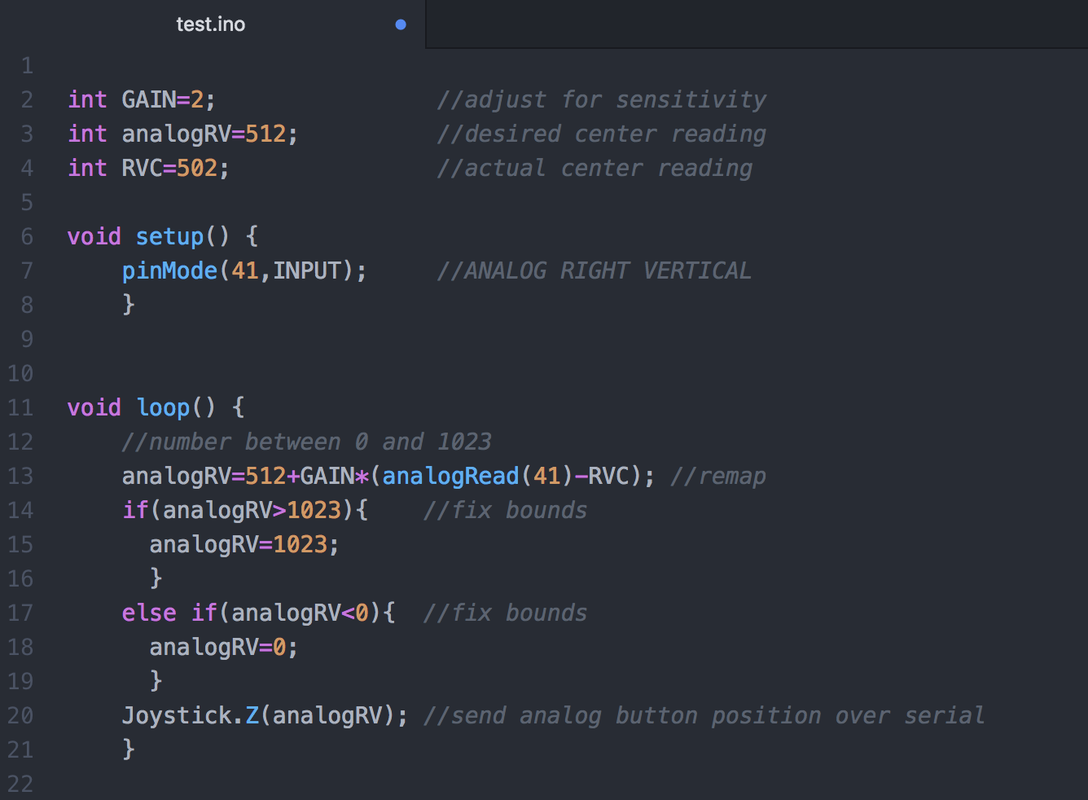
Analog Program Example
Raspberry Pi Backlight:
To adjust brightness you can youse the CLI and type echo n > /sys/class/backlight/rpi_backlight/brightness with root privilege. Where n is a value 0 to 255.
If you want the brightness set at a specific level every time the Pi starts up. You can add the command to your local.rc profile which is read every time the Pi boots.
open it with:
sudo nano /etc/rc.local
before the line exit 0 add the commands below that allow r-w-x privileges to all users and modify the brightness level (I like mine at 50):
sudo chmod 777 /sys/class/backlight/rpi_backlight/brightness
sudo echo 50 > /sys/class/backlight/rpi_backlight/brightness
type ctrl+x and y (enter) to save and close
Remove Lightning Bolt Power Overlay:
To disable this from showing up. Add the following to /boot/config.txt:
sudo nano /boot/config.txt
add at the bottom
avoid_warnings=1
To disable this from showing up. Add the following to /boot/config.txt:
sudo nano /boot/config.txt
add at the bottom
avoid_warnings=1
Setting up SSH on the PI:
To set this up launch the Raspberry Pi configuration menu with:
sudo raspi-config
5 Interfacing Options -> P2 SSH -> Enable
reboot
get IP address with: (its called inet addr)
ifconfig
on another device you can access the pi with
ssh pi@<ipaddress>
by default the parameters
username: pi
password: raspberry
to keep the wireless running over extended periods of time run
sudo iw wlan0 set power_save off
Setting up vim on the PI:
To get vim text editor run the following:
sudo apt-get update
sudo apt-get install vim-runtime
sudo apt-get install vim
Create a file called .vimrc to set the following configurations:
vim ~/.vimrc
set number
set expandtab
set tabstop=4
To get vim text editor run the following:
sudo apt-get update
sudo apt-get install vim-runtime
sudo apt-get install vim
Create a file called .vimrc to set the following configurations:
vim ~/.vimrc
set number
set expandtab
set tabstop=4
Autolaunching programs
Modify the following:
/etc/rc.local: executes when the system boots
./bash_profile: executes when a user logs in
~/.bashrc: executes when a user starts a bash shell
Modify the following:
/etc/rc.local: executes when the system boots
./bash_profile: executes when a user logs in
~/.bashrc: executes when a user starts a bash shell
Triggerhappy Daemon is used to control volume and screen brightness with buttons as well as powering down the pi. When a certain button combination is pressed the Daemon will execute the corresponding command.
get the daemon package with:
sudo apt-get install triggerhappy
open the configuration file with
sudo nano /etc/init.d/triggerhappy
modify the configuration file line to look like the following
DAEMON_ARGS="--daemon --triggers /etc/triggerhappy/triggers.d/ --socket /var/run/thd.socket --pidfile $PIDFILE --user pi /dev/input/event*"
now you can create your configuration file which specifies the button press and commend to execute following it.
To do this I created a script in /etc/triggerhappy/triggers.d/ called volumectrl.conf
sudo nano /etc/triggerhappy/triggers.d/volumectrl.conf
Inside I wrote the following:
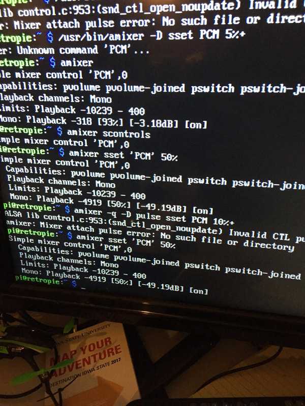
KEY_1 1 amixer sset 'PCM' 40%
KEY_2 1 amixer sset 'PCM' 60%
KEY_3 1 amixer sset 'PCM' 80%
KEY_4 1 amixer sset 'PCM' 90%
KEY_5 1 amixer sset 'PCM' 100%
KEY_X 2 sudo shutdown -h now
KEY_A 1 sudo chmod 777 /sys/class/backlight/rpi_backlight/brightness && echo 25 > /sys/class/backlight/rpi_backlight/brightness
KEY_B 1 sudo chmod 777 /sys/class/backlight/rpi_backlight/brightness && echo 50 > /sys/class/backlight/rpi_backlight/brightness
KEY_C 1 sudo chmod 777 /sys/class/backlight/rpi_backlight/brightness && echo 75 > /sys/class/backlight/rpi_backlight/brightness
KEY_D 1 sudo chmod 777 /sys/class/backlight/rpi_backlight/brightness && echo 100 > /sys/class/backlight/rpi_backlight/brightness
KEY_E 1 sudo chmod 777 /sys/class/backlight/rpi_backlight/brightness && echo 150 > /sys/class/backlight/rpi_backlight/brightness
KEY_F 1 sudo chmod 777 /sys/class/backlight/rpi_backlight/brightness && echo 200 > /sys/class/backlight/rpi_backlight/brightness
To figure out what button was being pressed I played around with the utility
thd --dump /dev/input/event*
It prints the buttons being pressed. The numbers stand for 0=release 1=press 2=hold. (Press ctrl+c to kill)
Lastly, restart the daemon for the changes in volumectrl.conf to take effect
sudo service triggerhappy restart
In the future while working in the CLI it may be helpful to use sudo service triggerhappy stop, you will understand why!
get the daemon package with:
sudo apt-get install triggerhappy
open the configuration file with
sudo nano /etc/init.d/triggerhappy
modify the configuration file line to look like the following
DAEMON_ARGS="--daemon --triggers /etc/triggerhappy/triggers.d/ --socket /var/run/thd.socket --pidfile $PIDFILE --user pi /dev/input/event*"
now you can create your configuration file which specifies the button press and commend to execute following it.
To do this I created a script in /etc/triggerhappy/triggers.d/ called volumectrl.conf
sudo nano /etc/triggerhappy/triggers.d/volumectrl.conf
Inside I wrote the following:
KEY_1 1 amixer sset 'PCM' 40%
KEY_2 1 amixer sset 'PCM' 60%
KEY_3 1 amixer sset 'PCM' 80%
KEY_4 1 amixer sset 'PCM' 90%
KEY_5 1 amixer sset 'PCM' 100%
KEY_X 2 sudo shutdown -h now
KEY_A 1 sudo chmod 777 /sys/class/backlight/rpi_backlight/brightness && echo 25 > /sys/class/backlight/rpi_backlight/brightness
KEY_B 1 sudo chmod 777 /sys/class/backlight/rpi_backlight/brightness && echo 50 > /sys/class/backlight/rpi_backlight/brightness
KEY_C 1 sudo chmod 777 /sys/class/backlight/rpi_backlight/brightness && echo 75 > /sys/class/backlight/rpi_backlight/brightness
KEY_D 1 sudo chmod 777 /sys/class/backlight/rpi_backlight/brightness && echo 100 > /sys/class/backlight/rpi_backlight/brightness
KEY_E 1 sudo chmod 777 /sys/class/backlight/rpi_backlight/brightness && echo 150 > /sys/class/backlight/rpi_backlight/brightness
KEY_F 1 sudo chmod 777 /sys/class/backlight/rpi_backlight/brightness && echo 200 > /sys/class/backlight/rpi_backlight/brightness
To figure out what button was being pressed I played around with the utility
thd --dump /dev/input/event*
It prints the buttons being pressed. The numbers stand for 0=release 1=press 2=hold. (Press ctrl+c to kill)
Lastly, restart the daemon for the changes in volumectrl.conf to take effect
sudo service triggerhappy restart
In the future while working in the CLI it may be helpful to use sudo service triggerhappy stop, you will understand why!


Device Screen Select:
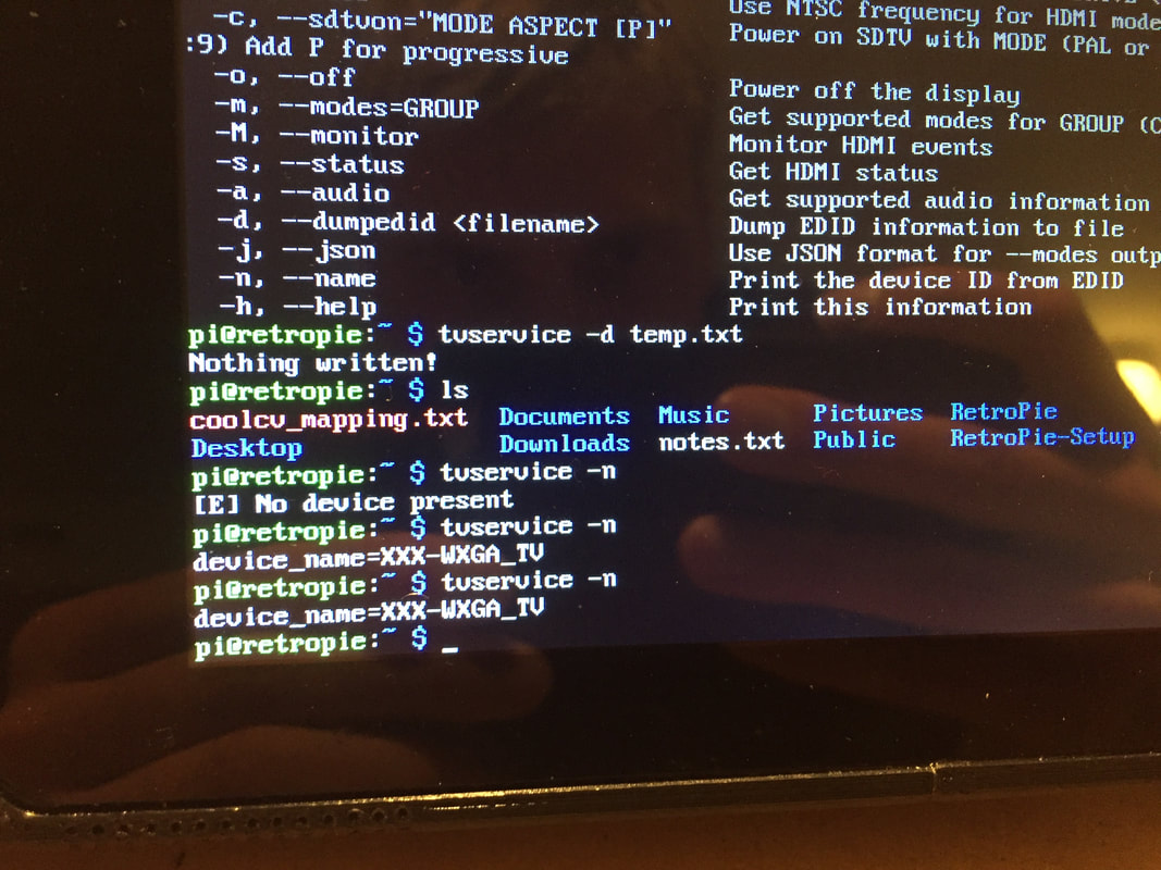
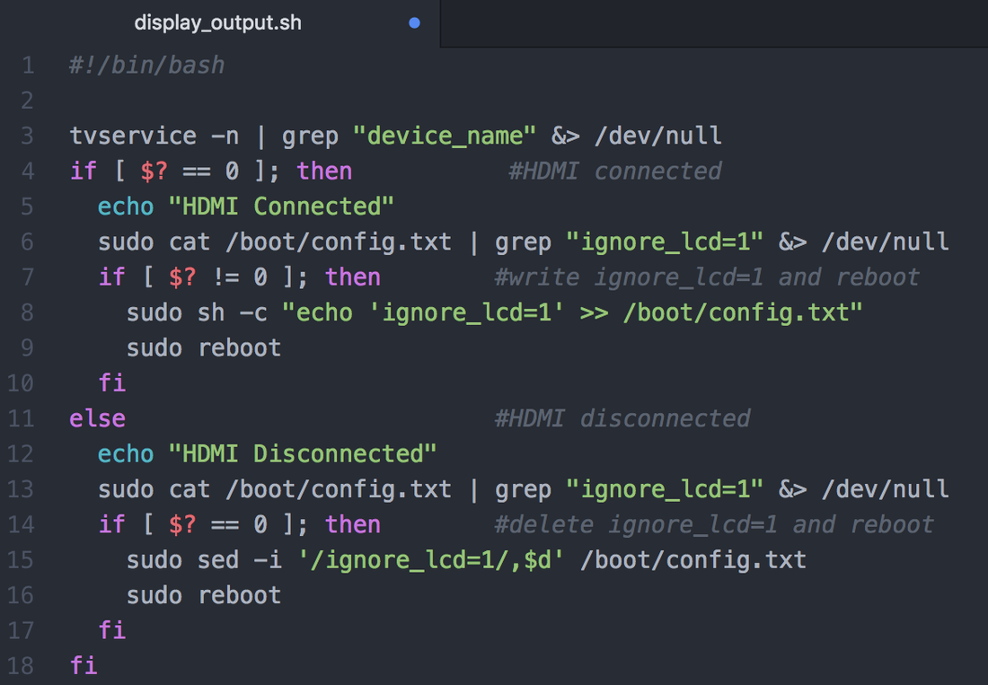
I needed to program the behavior of outputting video to the 7inch touch screen by default and to the TV when an HDMI is plugged in. This took quite a bit of research. Since I am using a Pi 3 I cannot simply read the HDMI pin 19 off the GPIO pins. I worked around this issue by reading the output from the command tvservice -n to check if HDMI is connected. My script decides from the return value to place ignore_lcd=1 into /boot/config.txt or remove it. If a altering of config.txt takes place, my script reboots the system for it to take affect. The script is run on boot by being placed in /etc/rc.local which requires you to have the device you want it to work for plugged in before you turn the device on.
To set it up on the Pi: git clone https://github.com/timlindquist/rpi_display_output.git
get directory of rpi_display_output.sh (for me its /home/pi/rpi_display_output/display_output.sh)
add permission to all users with sudo chmod 777 /home/pi/rpi_display_output/display_output.sh
Now it is time to edit the boot script sudo nano /etc/rc.local before exit 0 add the path to the script (for me its /home/pi/rpi_display_output/display_output.sh)
save and exit ^x y enter
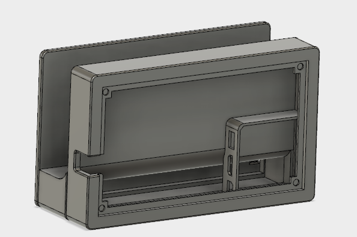
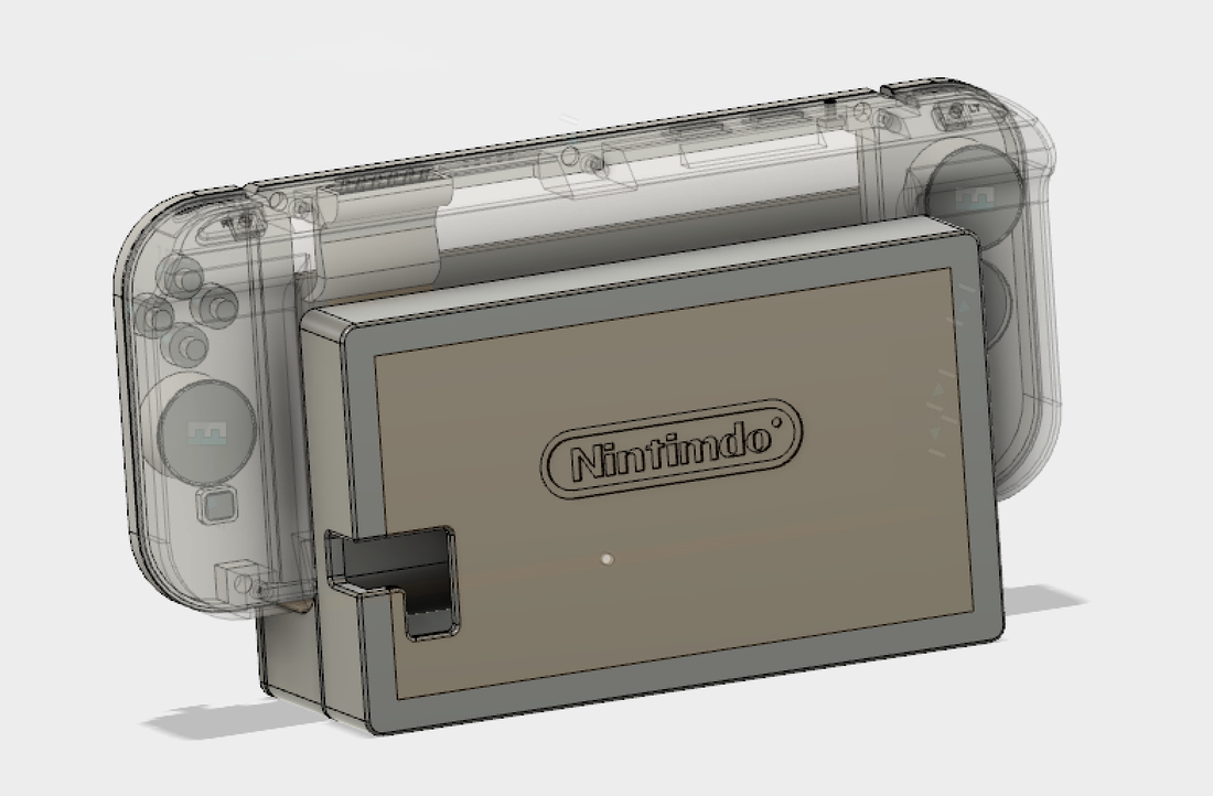
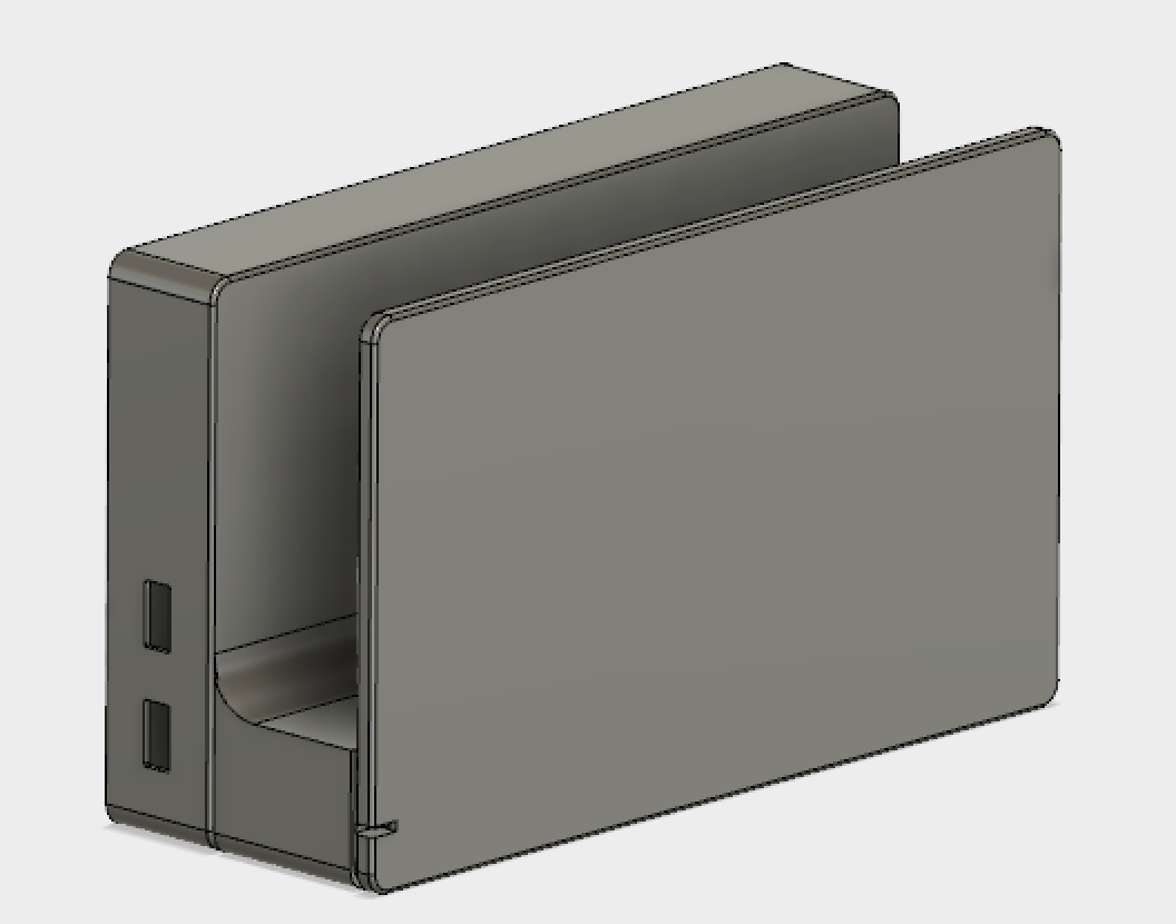
Dock:
This build wouldn't be complete without a dock for charging and easy TV hookup so I designed one in the pictures below. The 3D models are available with the others in my Github package.
This build wouldn't be complete without a dock for charging and easy TV hookup so I designed one in the pictures below. The 3D models are available with the others in my Github package.
|
Please let me know if you have any questions in the comment section below, I am happy to help. I will update this instructional periodically if there any noticeable areas of confusion.
Have fun building! -Tim |

|
Comment Form is loading comments...
