Introduction:
|
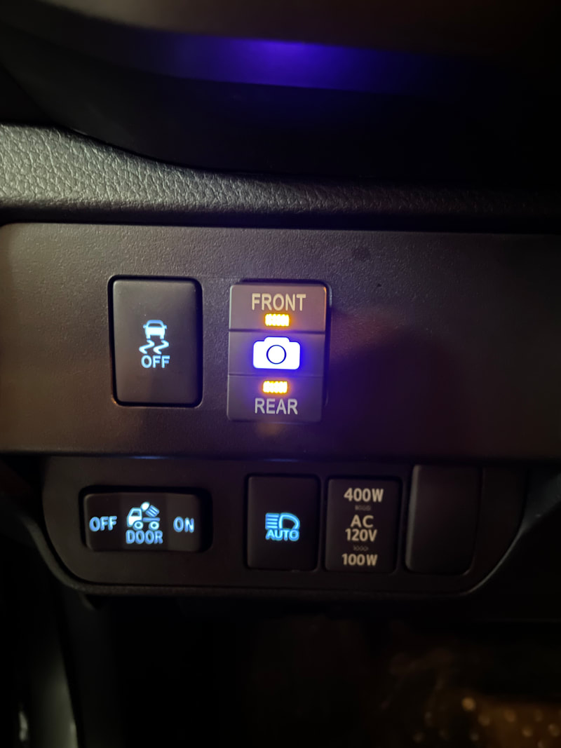
This project was to do a couple modifications to the Anytime Backup Camera Switch.
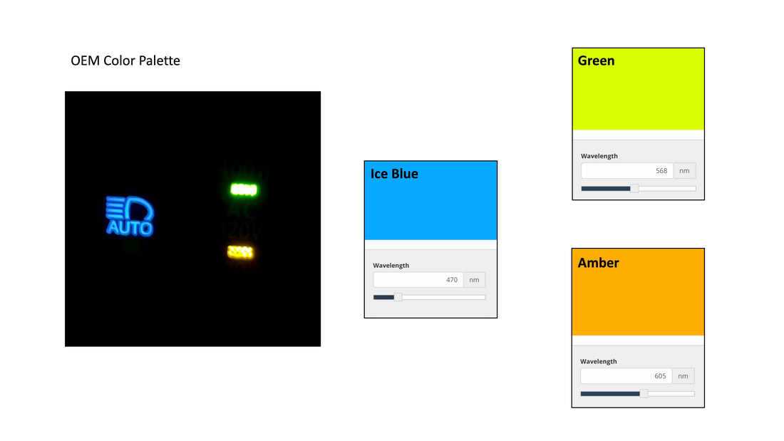
https://www.anytimebackupcamera.com/ Buy a Modified Switch: If you're not comfortable doing the modification I provided a purchase link on the right. **Note if you select "Existing", I will reach out to you with shipping information (include your email). Product: New / Existing Standby LED Color: see before/after photos Front/Rear LED Color: see before/after photos Things I wanted to change: 1. The toggle illuminates both FRONT and REAR LED when FRONT is selected. 2. The standby blue LED does not match the Toyota Tacoma OEM Ice Blue. 3. FRONT and REAR LED are OEM Amber color, I want them to match the OEM Green color |
|
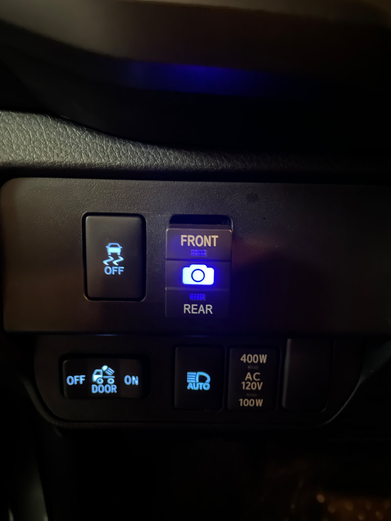
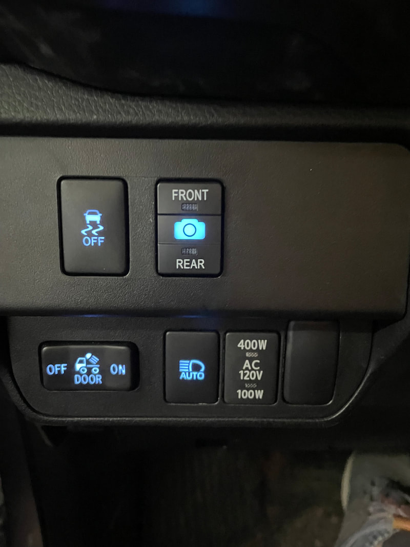
Before:
Standby LED: Blue (no change)
Front/Rear LED: Amber (no change)
Depending on which version of the switch you have, the blue standby LED is either a Royal Blue (on switches with a green PCP and 6 plug pins) or Cyan Blue (on switches with a black PCB and 4 plug pins). The switches blue does not match the Tacoma's standby OEM Ice Blue LED's.
|
|
|
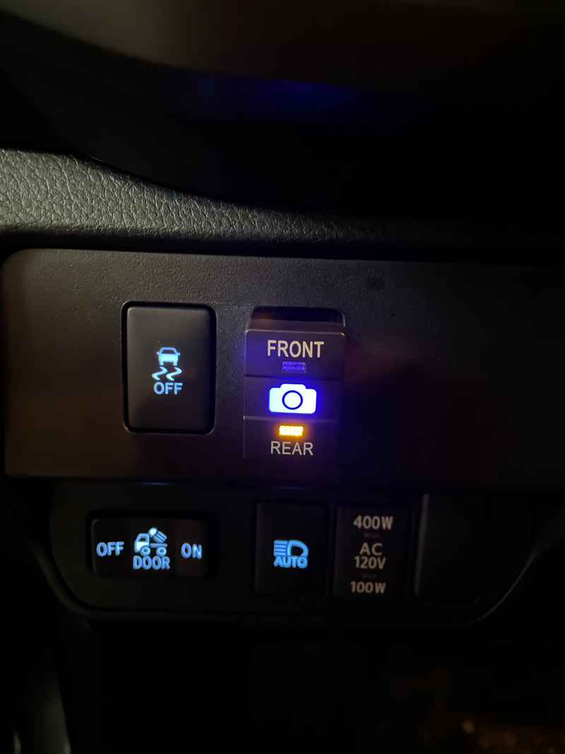
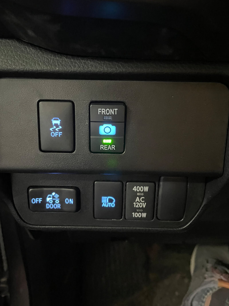
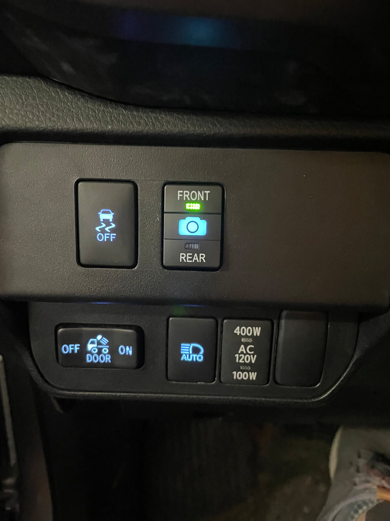
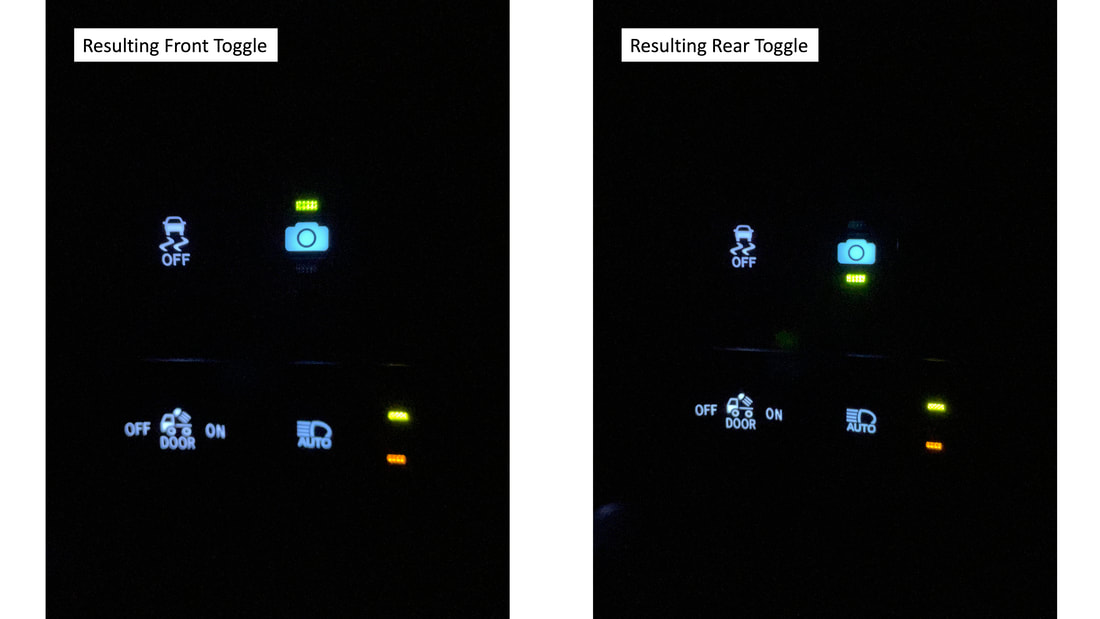
After:
Standby LED: Ice Blue (modification)
Front/Rear LED: Green (modification)
Front/Rear LED: Green (modification)
|
|
|
Color Matching
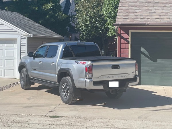
The following color matching was done in reference to a 2023 Toyota Tacoma.
|
|
|
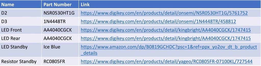
Parts List
|
The following is a parts list I used for these modifications.
** Tip: when ordering parts from places like Digikey order some extra incase you drop or incorrectly solder your only one. Sometimes there's even a price break for ordering more. |
|
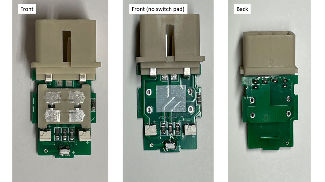
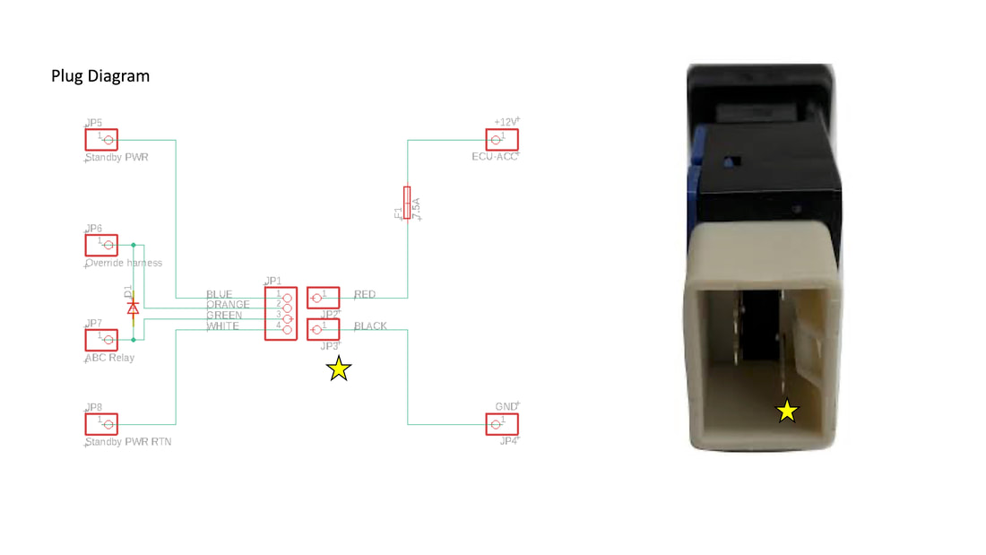
Reverse Engineering the Switch
I unsoldered the pad to get a better look at the PCB traces underneath. This allowed me to figure out how everything was wired. I translated this into the schematics below.
|
|
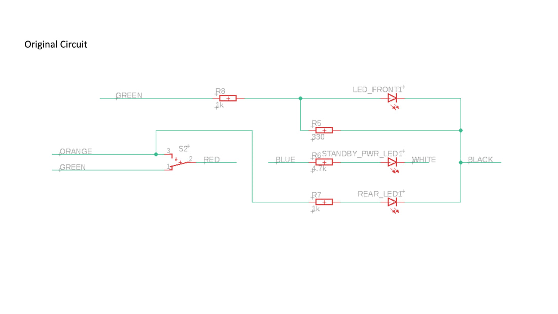
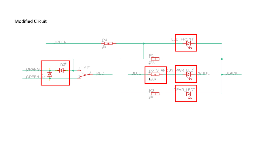
Modifications
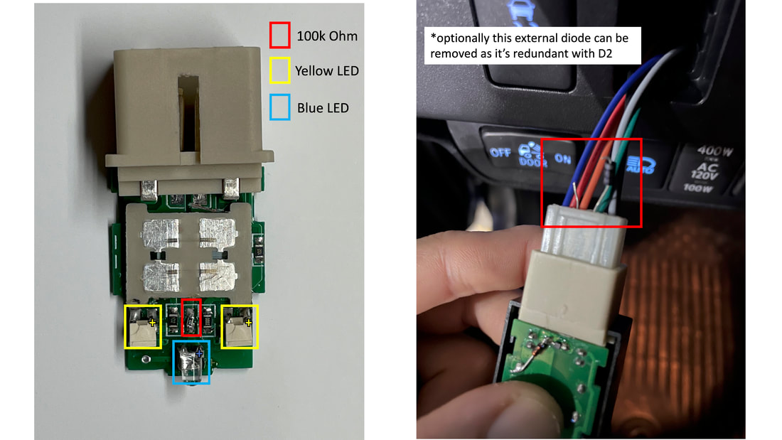
Below shows the things I modified (red boxes)
- (optional) Add Diode 2 between GREEN and ORANGE. This is redundant with the external Diode shown in one of the pictures below. I just wanted it inside the package so did this.
- Add Diode 3 inline with the ORANGE and switch S1
- Replace the standby LED resistor R2 with a 100k ohm surface mount resistor
- Replace the standby power LED with the Ice Blue 3mm through hole LED (polarity: Longer leg: +, Shorter leg: GND).
- Replace the FRONT and REAR LED with the GREEN boomerang LED
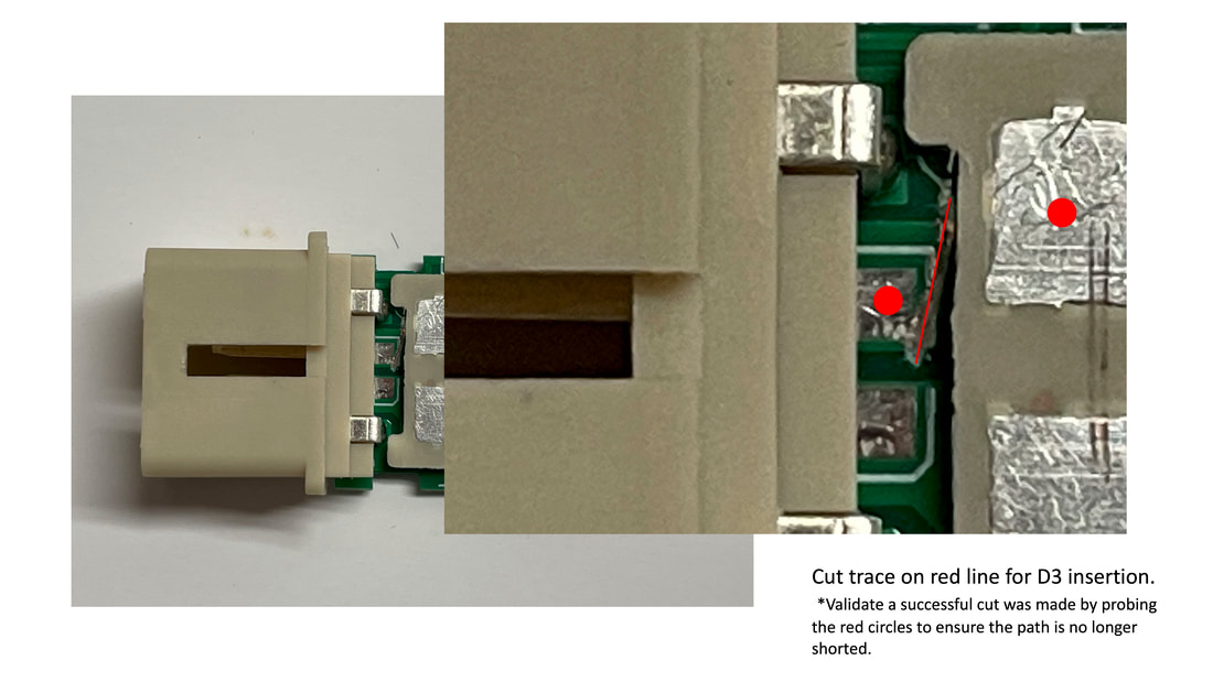
The image below shows how we insert a diode into step 2. It requires cutting the PCB trace to open part of the circuit where we are going to insert the diode D3. This cut is possible without removing the switch plate.
- Carefully use a razor blade to cut along a grove along the red line.
- Test that the circuit is open by measuring continuity between the red dots.
|
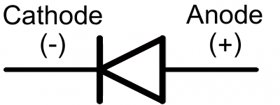
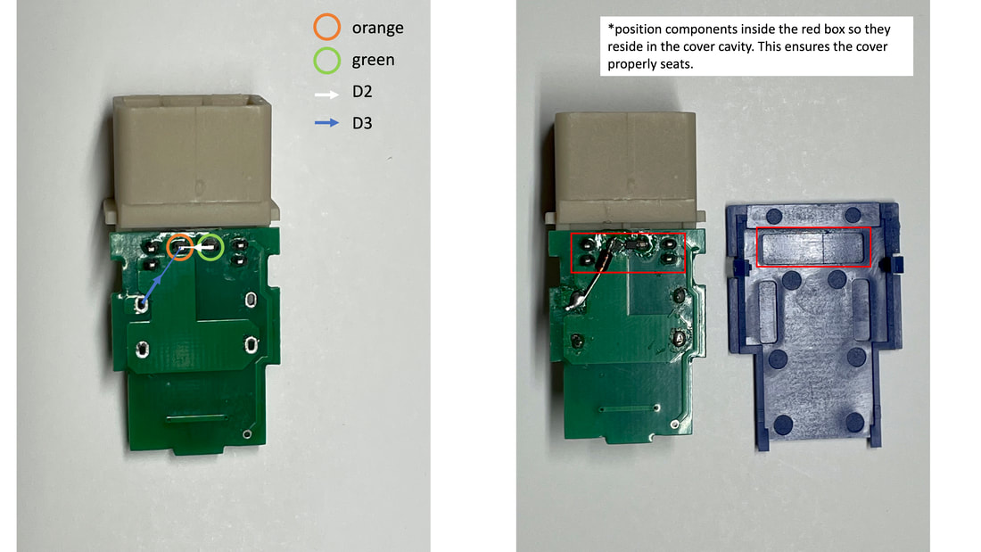
Next flip the PCB over and solder the diode D3 from the switch S1 pin to the ORANGE pin.
Ensure the diode D3 is correctly oriented by:
(optional) Solder the diode D2 between the GREEN and ORANGE pin Ensure the diode D2 is correctly oriented by:
|
|
The diagram below left shows where the resistor and LED's should replace the existing components. Notice the + for the LED's which indicates where the positive polarity of the LED should go.
** Tip: a fat soldering tip is useful for getting the boomerang LED's disconnected.
The diagram below right shows the external diode which you can remove if you decided to add the diode D2
** Tip: a fat soldering tip is useful for getting the boomerang LED's disconnected.
The diagram below right shows the external diode which you can remove if you decided to add the diode D2
Disclaimer
I am not responsible for any incorrectly wired switches or damages caused by switch misuse.
Comment Box is loading comments...
