Introduction:
In this project, I explore how synthesizers originated as well as the various techniques available for complex signal generation. The primary synthesis techniques researched were Additive, Subtractive, Frequency Modulation, and Sample-Based Synthesis. After extensive background information was examined, a series of MATLAB scripts were created to verify the synthesis implementation and demonstrate understanding.
Following this, I set out to design my own hybrid synthesizer using a combination of the various techniques learned. The synthesizer created is a polyphonic composition device capable of audio generation as well as audio manipulation. It demonstrates core principles from each of the researched techniques to enable endless possibilities for the user. In the following pages, I explain the development process underwent to create this device and the details behind the unique designs.
Following this, I set out to design my own hybrid synthesizer using a combination of the various techniques learned. The synthesizer created is a polyphonic composition device capable of audio generation as well as audio manipulation. It demonstrates core principles from each of the researched techniques to enable endless possibilities for the user. In the following pages, I explain the development process underwent to create this device and the details behind the unique designs.
Background:
An audio synthesizer is an electronic device that generates electrical signals to imitate traditional musical instruments or construct unique sounds. What makes synthesizers distinct compared to other electric instruments is that synthesizers have a wide range of versatility as a result of the many available circuit module configurations. In contrast, an electrical instrument, such as a keyboard or theremin, would generally be used for a set function in generating a specific sound.
Synthesizers first began appearing in the 1950's and gained popularity to become the iconic sound of pop music in the 1970's. Today, synthesizers are even more prevalent in driving music composition. One of the earliest considered synthesizers was a machine by RCA called the “Mark II Sound Synthesizer” that was developed for researching audio properties. It was the first programmable synthesizer capable of generating tones and sequences to a high degree of precision. However, as solid-state electronics emerged the large Mark II machine, due to vacuum tube technology, was quickly considered obsolete. This prompted a shift to an integrated modular design proposed by Harald Bode. His idea was to break the design down into specialized modules that would allow modification on a single characteristic of the signal. Robert Moog soon adopted these ideas to develop a portable device that was advantageous to musical composers, gaining it much attention. As computational progress continued, the focus began to shift from the analog to the digital realm by using digital signal processing hardware and virtual software tools.
Synthesizers first began appearing in the 1950's and gained popularity to become the iconic sound of pop music in the 1970's. Today, synthesizers are even more prevalent in driving music composition. One of the earliest considered synthesizers was a machine by RCA called the “Mark II Sound Synthesizer” that was developed for researching audio properties. It was the first programmable synthesizer capable of generating tones and sequences to a high degree of precision. However, as solid-state electronics emerged the large Mark II machine, due to vacuum tube technology, was quickly considered obsolete. This prompted a shift to an integrated modular design proposed by Harald Bode. His idea was to break the design down into specialized modules that would allow modification on a single characteristic of the signal. Robert Moog soon adopted these ideas to develop a portable device that was advantageous to musical composers, gaining it much attention. As computational progress continued, the focus began to shift from the analog to the digital realm by using digital signal processing hardware and virtual software tools.
Synthesis Techniques:
Additive Synthesis:
Additive synthesis is the process of constructing sound by adding a multitude of waveforms together. It works similar to the concept of Fourier Series by expressing a periodic signal as a sum of weighted sinusoids. To understand the effect higher order harmonics have on sounds, it is helpful to explore the difference between a piano note A3 versus a guitar note A3. Both notes are represented by their fundamental frequency 220 Hz but the timbre of a piano sounds very different from the timbre of a guitar. An observable difference can easily be recognized in the time domain representation of the signals as shown in Figure 1. The time domain representation of the waveform is shown on the left giving the unique shape for that particular instrument. On the right, the peaks depict the frequency content making up that signal all sharing a common fundamental. The unique audio shape of each instrument is a direct result of the weight terms of the harmonic components that are then summed together. With this principle in mind, it is possible to create any periodic sound by adding sinusoidal harmonic components at different amplitudes together to form the desired timbre, see Figure 2.
Additive synthesis is the process of constructing sound by adding a multitude of waveforms together. It works similar to the concept of Fourier Series by expressing a periodic signal as a sum of weighted sinusoids. To understand the effect higher order harmonics have on sounds, it is helpful to explore the difference between a piano note A3 versus a guitar note A3. Both notes are represented by their fundamental frequency 220 Hz but the timbre of a piano sounds very different from the timbre of a guitar. An observable difference can easily be recognized in the time domain representation of the signals as shown in Figure 1. The time domain representation of the waveform is shown on the left giving the unique shape for that particular instrument. On the right, the peaks depict the frequency content making up that signal all sharing a common fundamental. The unique audio shape of each instrument is a direct result of the weight terms of the harmonic components that are then summed together. With this principle in mind, it is possible to create any periodic sound by adding sinusoidal harmonic components at different amplitudes together to form the desired timbre, see Figure 2.
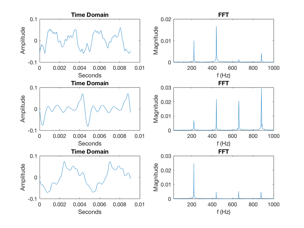
Figure 1: Waveform and Spectrum of multiple instruments sharing same fundamental frequency 220 Hz (top: piano, middle: french horn, bottom: guitar).
|
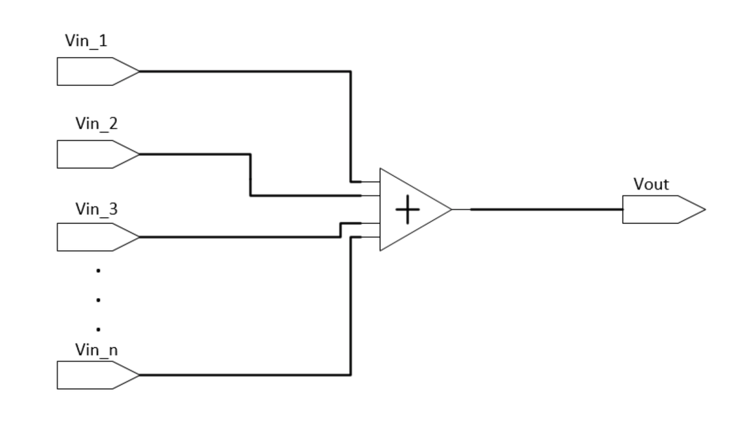
Figure 2: Additive Synthesis Process
|
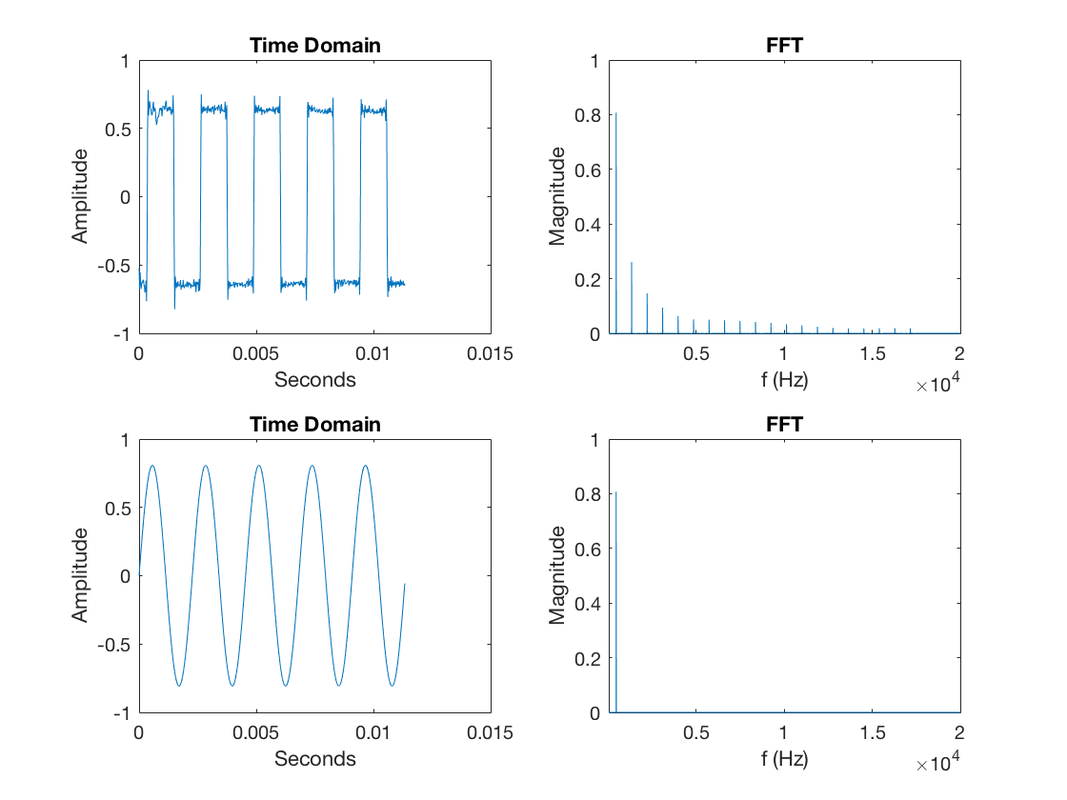
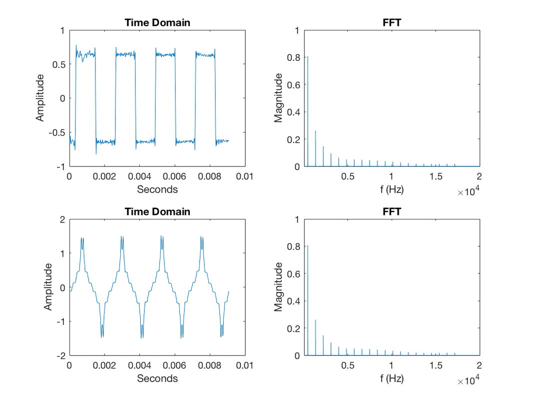
The additive synthesis technique was explored through a MATLAB script. It is written to decompose periodic audio signal (taken as input from a .mp3) into their frequency and magnitude components then reassemble using N number of parameterized sinusoids. It was interesting to see just how many of the frequency components were truly required to get a sound remotely like the original. With a scalable ranking system based on a frequencies magnitude, (higher magnitude of component → greater impact on periodic shape), it was easy to adjust the output of the program to see varying effects. When looking at a square wave, it was found that 10 sinusoids could represent the periodic input waveform with reasonable fidelity. At N=10 the sounds were nearly indistinguishable from one another and had a similar time domain shape. In Figure 3 MATLAB plots, row one represents the original input signal time domain and frequency content. Row two shows the reconstruction using N dominant sinusoids in the time and frequency domain.
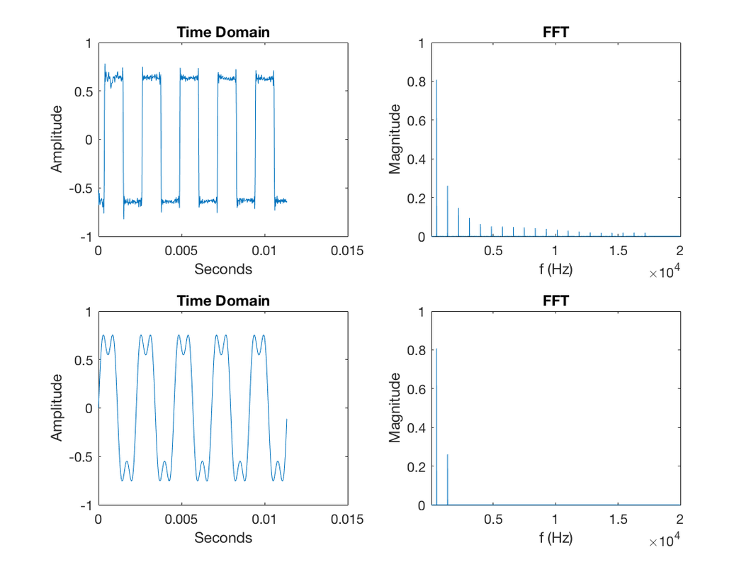

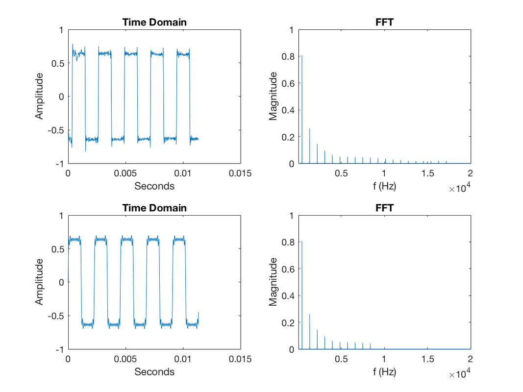
During this process, getting the phase term correct for each sinusoid was only needed to represent the visual time domain waveform in the same manner. It was observed that phase had little effect on how the output waveform sound was perceived. This is shown in Figure 4 where N is 100. In the plot with a random phase, the time domain signal looks nothing like the original square wave shape. However, after hearing both tones, they are perceived to be the same because the frequency content is still identical. The only effect constant phase has on your ears is loudness as a result of the constructive and destructive interference:sin(ω*t)+sin(ω*t+pi)=0. Additive synthesis becomes a resource intensive technique due to its requirement of hardware oscillators to form each sinusoid. Alongside this, it is difficult to create an ideal oscillator with one harmonic component.

Subtractive Synthesis:
Subtractive synthesis is the process of removing certain frequencies from a base waveform rich in frequency content. The process for this technique begins with generating a base waveform through the use of an oscillator circuit. The output of the circuit will be a periodic waveform such as a square wave. That signal is then piped into a filter network that attenuates targeted frequencies through the use of low pass and high pass filters. Finally, the signal is passed through an amplifier which has its gain controlled by an Attack, Decay, Sustain, Release (ADSR) envelope to produce an amplitude adjustment in the time-domain.
The ADSR profile is made to mimic the real life change in note amplitude, see Figure 5. When the note is struck the amplitude spikes over the duration of the attack time. Following attack, comes a decay stage transitioning into the steady state sustain region. Finally, the note rolls off when the key is released [6]. All four parameters can be manipulated to create a variety of different profiles. Behind all of this is often a Low-Frequency Oscillator (LFO) and digital timers used to control parameters [2].
The subtractive synthesis technique was the main method of synthesis for early monophonic keyboards and is associated with the classic synthesizer sound. It was pioneered by Donald Buchla and Robert Moog in the 1960's through 1970's [3]. The ADSR amplifier was simulated using a constructed MATLAB program that converted event times into a linear transitioned amplitude vector. This vector was then multiplied by the input waveform, in this case, a square wave at 440 Hz was used to produce the desired output amplitude profile varying in time shown in Figure 6.
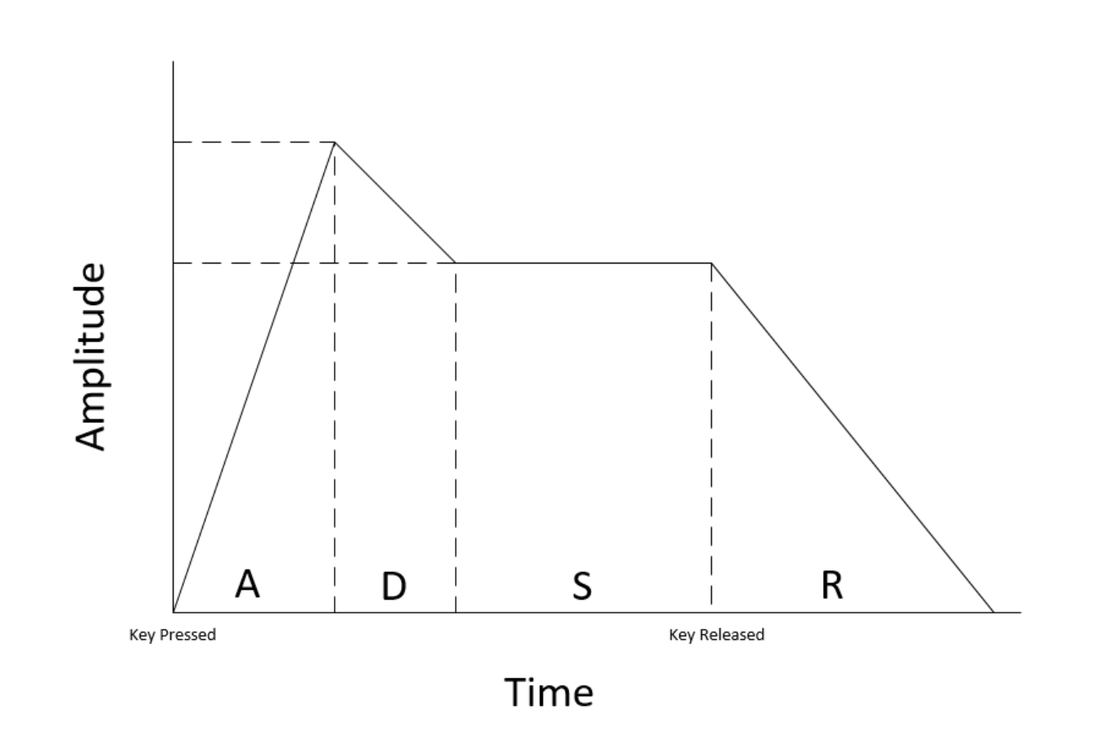
Figure 5: ADSR Envelope
|
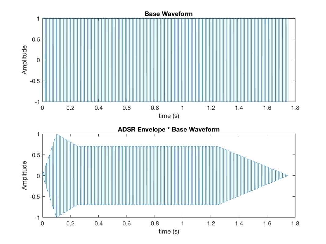
Figure 6: MATLAB ADSR Amplifier
|
FM Synthesis:
Frequency modulation (FM) synthesis was developed by John Chowning when he discovered unique audio characteristics in modulating audible frequencies with other frequencies. The effect was the formation of rich harmonic content from the resulting frequency sidebands. The technique for FM synthesis is formed by two or more oscillators known as the modulators and a carrier. The modulator is an operator which is performing the modulation. The carrier is an operator that is being modulated on. When the carrier is modulated it creates a series of harmonics, when the modulator changes pitch the harmonics shift accordingly [3]. Staging these modules allows for the recreation of many realistic sounding musical instruments. The patent for the FM Synthesis technique was licensed by Yamaha and integrated into many of their electronic musical devices, such as the YM2612 integrated circuit being used [8].
Frequency modulation equation: f(t)=A*sin(2*π*C*t+D*sin(2*π*M*t))
A = carrier amplitude
C = carrier frequency
D = modulator amplitude
M = modulator frequency
Index of modulation: I=D/M
I+1 = roughly the number of significant harmonics [4].
In Figure 7, I demonstrate the interactive MATLAB script to control parameters for the carrier’s amplitude and frequency, as well as the modulator's amplitude and frequency. The top left knob controls the carrier's frequency with a drop-down on the right for a frequency multiplication factor, the knob to the right controls the magnitude of the signal. Likewise, the modulator controls follow this same convention on the bottom row. The chart displayed on the right shows the time domain and frequency content of the different signals. The play button plays the FM Output signal for three seconds.
By manipulating parameters through knob combinations, it can be observed that a higher magnitude in the modulator has an impression on the FM Output by creating a wider spread of frequencies on the harmonic nodes. An increase in the modulator's frequency shifts the harmonic node bundles outward in the resulting FM Output. When modulating the carrier with a harmonic frequency produces a wider chorus sound whereas modulating with a non-harmonic frequency produces a harsh percussion sound.
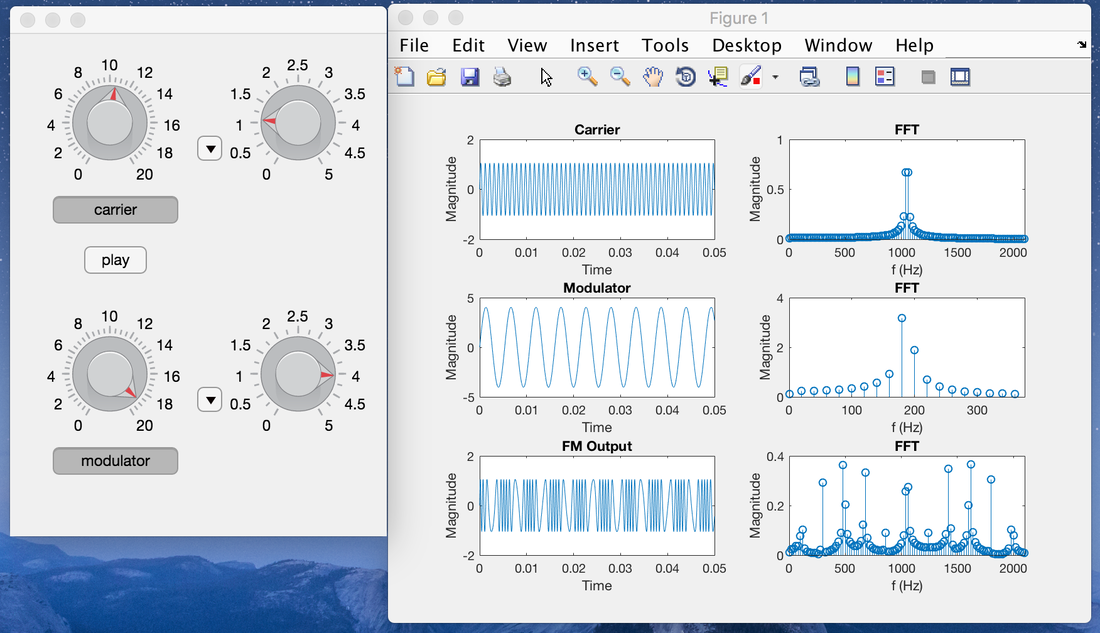
Figure 7: Carrier= 1Vp @ 1000Hz, Modulator=4Vp @ 180Hz
|
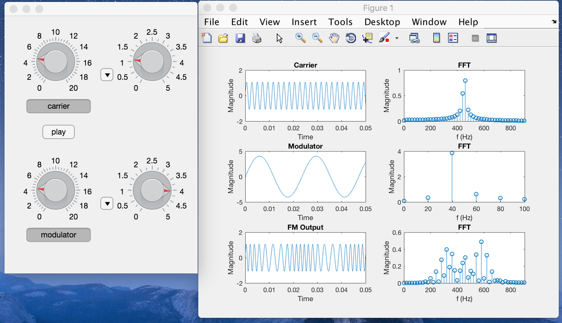
Figure 7: Carrier= 1Vp @ 450Hz, Modulator=4Vp @ 40Hz
|
Sample-based Synthesis:
Sample-based synthesis is the process of sampling instruments and then playing back the recorded audio. The benefit of this method is that you can reproduce distinct instrument sounds with high fidelity because it is a recording of the actual instrument. It also takes less hardware to implement as its main component is a digital to analog converter that translates the digital recorded data into an analog signal. A prerecorded seed for an instrument can be modified to taper or extend the duration of that note as if it were being played in real time. Sample-based synthesis is heavily used in Virtual Studio Technology (VST) plugins for an application where the synthesis is done in a software environment. Sampled sounds, such as drums, work very well for impulse based instruments because there is no need to modify the duration of the sample. This synthesis technique is also seen in soundboards where a button is linked to play a certain sound when pressed.
Sample-based synthesis is the process of sampling instruments and then playing back the recorded audio. The benefit of this method is that you can reproduce distinct instrument sounds with high fidelity because it is a recording of the actual instrument. It also takes less hardware to implement as its main component is a digital to analog converter that translates the digital recorded data into an analog signal. A prerecorded seed for an instrument can be modified to taper or extend the duration of that note as if it were being played in real time. Sample-based synthesis is heavily used in Virtual Studio Technology (VST) plugins for an application where the synthesis is done in a software environment. Sampled sounds, such as drums, work very well for impulse based instruments because there is no need to modify the duration of the sample. This synthesis technique is also seen in soundboards where a button is linked to play a certain sound when pressed.
Design:
The motivation for the synthesizer design was to take characteristic components from different synthesis techniques and mesh them all together in one hybrid synthesizer. The final product is a polyphonic composition device, able to simultaneously generate multiple independent sounds. This project was divided into three phases: background research, audio generation, and audio manipulation. The timeline of the project was six months, beginning in May 2018 and finishing in November 2018.
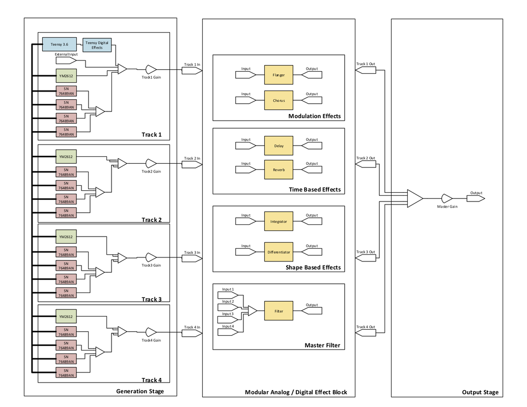
Figure 8: High-Level Block Diagram
In Figure 8, a high-level block diagram is shown that illustrates the approach for how the device was built. Beginning with the first stage, its primary use is to generate audio signals. The hardware in this block is divided into four tracks that are individually mapped to their own gain control slider. The purpose is to serve as an equalizer to be able to mix the different track volume levels. Inside a track resides channels. An individual channel is made up of 1, out of a possible 256, specific voices. In total there are 16 channels that can be mapped onto any of the tracks. A situation where this would be useful could happen if the user linked all the drum channels on track 1, treble channels on track 2 and base channels on track 3. Through this configuration, the user would later be able to control these categories with a gain slider. Behind all the hardware is a microcontroller that dictates scheduling when a resource is requested. In the case of insufficient hardware resources caused by heavy traffic, an fault light turns on indicating it is not able to perform the desired task.
The second stage is a modular effect block that is configured in a plugboard style layout. The user handles routing of the signals through mono 3.5mm audio cables to jump the track inputs to effect module inputs and direct the outputs to more effect module inputs or to the final output. This plugboard configuration allows the user to intuitively layer their effects and alleviates the need for complex hardware switching required to accomplish this flexibility. The types of effects available in this section are modulation, time-based and shaped-based blocks. A master filter is also provided to modify amplitudes of the audio signal at certain frequencies.
The final stage combines the effect module's outputs into a single signal and passes it through the final amplifier controlled by the master gain slider. The signal is then delivered to the speakers or audio output jack to be heard by the user.
Audio Generation
Teensy 3.6
The Teensy 3.6 was the microcontroller chosen as the main controller for the digital circuitry. It has a 32-bit ARM processor being clocked at a frequency of 180 MHz and 50 I/O pins making it ideal for the resource intensive task. The microcontroller is also capable of being a master for the communication with the slave keyboard which allows the system to take external MIDI commands as input. A 32Gb SD card is used to store audio samples of various instruments for when sample-based synthesis is being used. Another responsibility of the Teensy is to generate various analog waveforms for use such as sine, square, sawtooth, triangle, and a 256 defined sample and hold. It is able to accomplish this with two DAC output ports. The microcontroller operates at 3.3V so appropriate logic level conversion circuits are needed to interface with several peripheral IC’s. The main software is loaded into the microcontroller’s program memory; it handles scheduling of notes on the different pieces of hardware, select line controls, and user input.
Yamaha YM2612
The Yamaha YM2612 is an audio generation integrated circuit that uses frequency modulation as its synthesis technique to mimic a number of musical instruments. This component is well known for being the main circuit responsible for audio in the Sega Genesis, game console. The chip uses four operator components to modulate the input frequency to end up with a complex waveform at the output. The four operators can be hooked together in a number of ways to produce different sounding instruments. Each configuration is referred to as an algorithm and is automatically set up in the voice selection for the user. Within each channel, there is an envelope which specifies the ADSR time-based shape. The registers that control all these parameters are configured through a 4-bit control bus with data on an 8-bit bus [5]. The reason I chose this chip was that it uses FM synthesis to produce a truly distinct sound recognizable to many. The master board allows for one chip per track to result in a total of four IC’s being utilized.
Texas Instruments SN76489AN
The TI SN76489AN is a Digital Complex Sound Generator (DCSG) capable of generating three square waves at different amplitude levels. Interfacing with the device is done over an 8-bit data bus that is controlled by a write enable signal. Data is transferred to the registers to specify a clock division amount and information on amplitude adjustment. The SN76489AN was featured in the Apple II sound card and game consoles of the 1980’s. The reason I chose this chip is for its simple interface, inexpensive cost, and ability to be readily used as an oscillator circuit with a rich frequency spectrum. The goal of this IC is to experiment with subtractive synthesis by filtering out components from the original waveform to produce a new sound.
Sequencer
An audio sequencer is a device to record repetitive patterns and play them back in a loop. It utilizes the sample-based synthesis technique by playing back impulse based recordings at a specific time. For my sequencer I wanted it to have 16th note resolution in a measure of music and be able to program and recall different layers to have multiple sequences running at once. The reason I wanted to use a single 16 button string to control multiple patterns is that it required fewer hardware resources and physical space. To relieve the Teensy microcontroller of demanding interrupts from any of the 16 button presses, I came up with the architecture in the sequencer schematic shown in Figure 9.
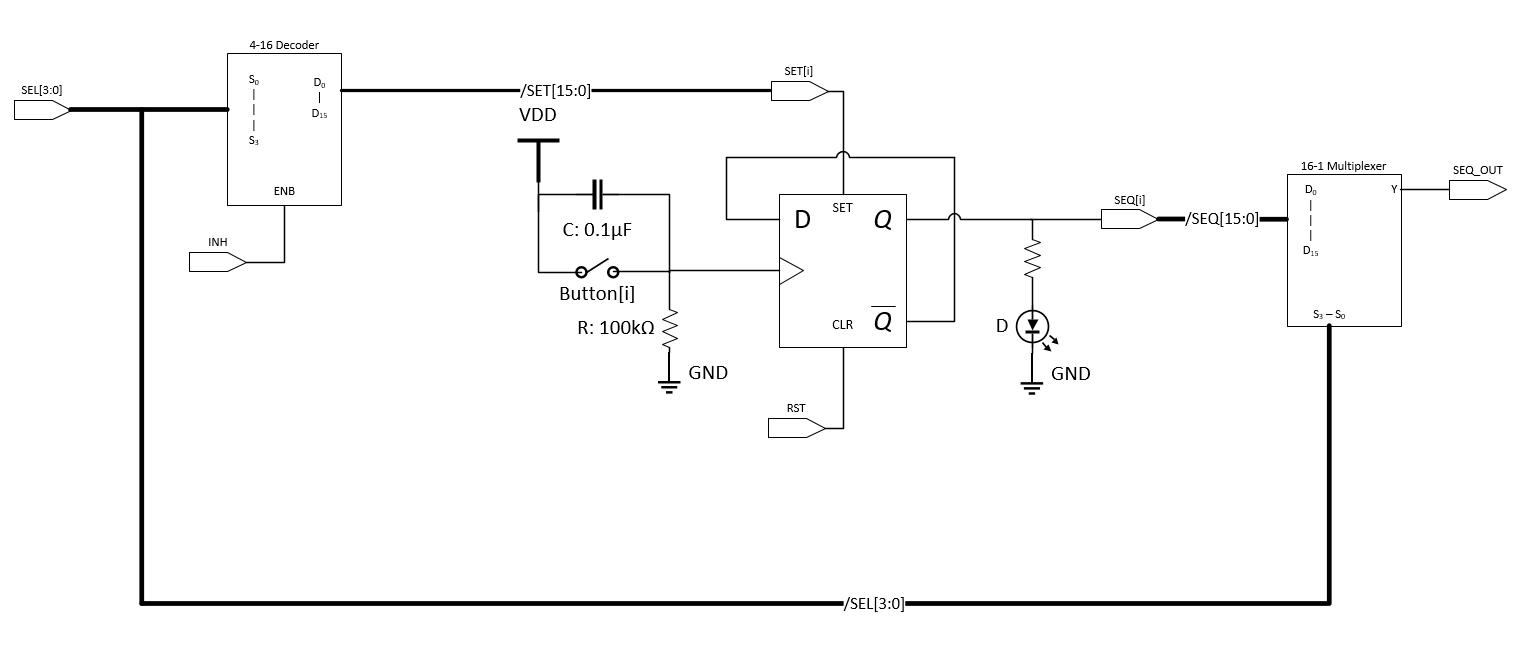
Figure 9: Single Sequence Schematic
My design for the sequencer used an asynchronous clock divide approach for storing the state of each sequence. Each of the push buttons generates a clock signal that is fed into a D flip-flop by passing VDD when pressed and GND when released. A 0.1uF capacitor was added across the switch to debounce, preventing an accidental clocking. The D flip-flop is configured with its negated output ~Q being fed back into the input D. This configuration divides the incoming clock signal by 2 and creates a toggle feature. If the button is pressed, the state will turn on/off the sequence ‘i’ and if you press it again it will turn off/on the sequence ‘i’. By doing this, it's easy for the user to create patterns and see in real time what they are developing since an LED is attached to the output Q of the D flip-flop.
This circuit is replicated 16 times to store a value for each of the positions in the sequence. Up until now the circuit described does not rely on any external input from the Teensy microcontroller. Interfacing with the sequencer is needed to load previously stored sequences and understand the programmed sequence of the user. Recalling the D flip-flop contents is done through the SET and RST signals that work independently from CLK. When SET is HIGH the value on Q becomes 1. When RST is HIGH the output on Q becomes 0. Steady state operation has SET=RST=0 and the metastable case SET=RST=1 is avoided. A reset is performed on all 16 D flip-flops synchronously by having the signal connected between them all. A SET is done on an individual D flip-flop level using a 4-16 decoder which will output HIGH for 1 SET signal out of the 16 SET signals if INH is LOW. When INH is HIGH the output of the 4-16 decoder is 0 for all 16 SET signals. With this in mind, we are able to program the 16-bit sequence externally.
The process for performing a program begins in steady state with INH=HIGH and RST=LOW. First, the sequence string must be cleared by toggling the RST to HIGH and back to LOW. After that, programming of the cells is done by setting all the ones in the sequence. This is accomplished by setting one bit at a time using the correct 4-bit SEL signal to correspond to the individual cell. Once selected the INH can be dropped LOW to write a 1 into the D flip-flop and INH back to HIGH to save the state.
In order to save the state of the 16-bit sequence, the outputs of the 16 D flip-flops must be read by the Teensy microcontroller. This is efficiently done by using a 16-1 Multiplexer that shares the 4-bit SEL lines with the 4 to 16 decoder. The 4-bit SEL signal is incremented from 0 to 15 with the output value SEQ_OUT being saved by the Teensy into a 16-bit sequence.
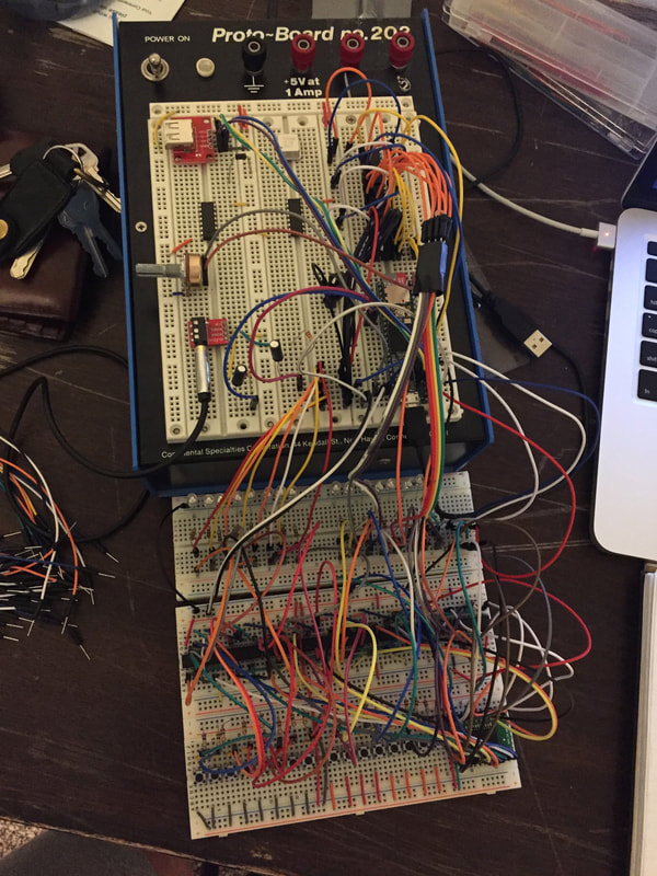
Figure 10: Synthesizer Prototype and Implementation
|
|
This hardware approach promotes efficient use of critical resources by only requiring the Teensy to read the sequence once per measure. It also allows the capability of creating multilevel patterns. The user can produce one sequence, switch to a different channel to develop another, then switch back and the old pattern is recalled. This creates an environment where you can create infinite layered patterns on a single 16 button sequence string. The microcontroller is only required to load a 16-bit string when the channel is changed. In total, it takes 7 pins from the Teensy to read and write a 16-bit pattern into the sequencer. This is highly favorable compared to doing it strictly in parallel which would have required 34 pins.
Audio Manipulation
Modulation Effects
Chorus
Chorus is an effect which replicates the input signal with a copy in similar pitch and a slight delay to alter the phase when adding the waveforms. This results in a fuller sound as if multiple instruments were playing simultaneously together to provide warmth to the track. The delay is usually controlled with a low-frequency oscillator, the more delay applied results in a wider sound. Chorus is implemented in the synthesizer by stacking channels with the same note progression at different volume levels to control how wet or dry the output signal will be.
Flanger
Flanger is created by mixing a signal of interest with a version of itself -slowed down or sped up. The result is a unique sound that sweeps in and out of depth. This effect is implemented digitally through the Teensy’s audio control system.
Time-Based Effects
Echo
Echo is created by continually delaying a copy of the input waveform and adding it back with the original at an altered amplitude. The implementation of the echo effect is often done through the use of a delay, feedback, and gain stage. This effect is incorporated in the synthesizer from a stand-alone echo processing IC. The delay time is controlled by a potentiometer which adjusts the voltage seen on the input pin of the IC to control an internal voltage controlled oscillator.
Delay
Delay is created by delaying one copy of the input waveform and adding it back with the original at an altered amplitude. The delay effect will also use the echo processing IC but it will not be configured in a feedback setup. A potentiometer is used to specify the delay amount which is a function of resistance.
Shape Based Effects
Differentiator
An active differentiator circuit produces an output signal corresponding to the rate of change of an input waveform multiplied by the gain. It is also useful for creating distortion by amplifying high frequency noise within a signal. The circuit is implemented by having the input waveform pass through a capacitor into the minus terminal of the op-amp along with a resistor connected in feedback from the output to minus terminal. The positive terminal is grounded. Below shows the equation for the output voltage in relation to the input.
Vout=-Rf*C*dVindt
Some characteristic shape translations of the differentiator circuit are: sin → cos, triangle → square, square → impulses.
Integrator
An active integrator circuit outputs the total area seen from a given input waveform as a function of time. The circuit for the integrator is implemented opposite of the differentiator with a capacitor in feedback and the resistor on the input stage. The equation for the output voltage in relation to the input.
Vout=-1Rin*C*0tVin dt
Some characteristic shape translations of the integrator circuit are: cos → sin, step → ramp, impulse → step.
ADSR Envelope
As explained previously, the ADSR envelope controls the gain, as a function of time, through the duration of a note. The ADSR envelope is found in multiple places in my project, the first is with the peripheral integrated circuits being used. When a note is played, the systems attack amplitude reach a level proportional to the velocity at which the note was struck. When the note is released the amplitude fades to zero at a rate corresponding to the sustain parameter. The envelope is also implemented digitally through the Teensy to provide access for the user to control all four ADSR parameters.
Signal Addition
For the plug based averaging nodes, I developed a dynamic input averaging circuit to guarantee the avoidance of signal saturation. The circuit is shown in Figure 11 and will always have a gain of Vout/Vin=-1/n*SUM(signal_i,i=1,n). This method takes advantage of the user physically plugging in signals to the summing stage. Each input and feedback resistor are identical in value. Feedback resistors are dynamically added to the system when a new signal is plugged in by having the ground of the 3.5mm cable control flow through transmission gates. Nodes on the input that are not being used remain floating and do not have an effect on the circuit. With this approach, it is guaranteed proportional averaging of any ‘n’ combination of added signals to the system will be obtained.
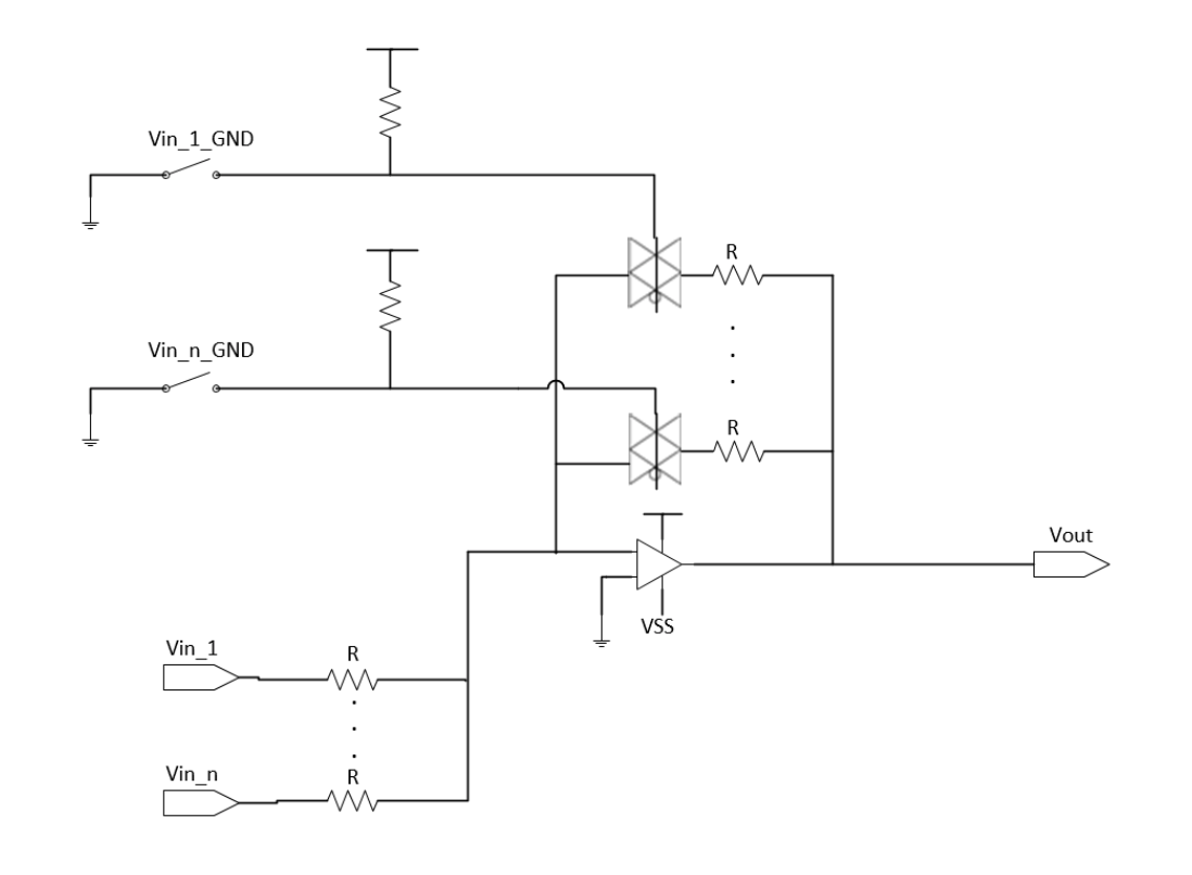
Figure 11: Dynamic Input Averaging Schematic
Filters
Filters are used to attenuate frequency content in a signal. Four common types of filters are: 1.) Low pass filter which decreases the magnitude of high-frequency signals while keeping the low frequency in tack. 2.) High pass filter which decreases the magnitude of low-frequency signals. 3.) Band-pass which attenuates all signals outside of a given frequency range. 4.) Band-stop which attenuates a given range of frequencies.
While building the filter module I wanted it to be all analog components and be overseen by a digital controller. The purpose of this was to simplify the user interface by eliminating a lot of knobs. By having it be analog components I was able to relieve the microcontroller from the resource-intensive task of filtering and be able to work in continuous time instead of with a sample signal.
The design for the filter module allowed the ability to produce low-pass, high-pass, band-pass and band-stop filters. Alongside this, the filters also have the capability to control the amplitude decay rate following the 3dB frequency. To do this I first developed a MATLAB program that could simulate my design by moving the corner frequency of the filters around and changing the order dynamically to adjust the rate of decay. The corner frequency was designed to sweep from 20 Hz to 20 kHz (audible hearing range) by changing resistance in the equation with a fixed capacitor value. Multiple signals were added together and fed into one another through the use of multiplexers and averaging circuits. In the MATLAB video below, the top knob controls the corner frequency of the low pass filter, likewise, the bottom controls the high pass filter. A drop-down menu changes the order of the filters. The other buttons enable the filters and configure them in a series or parallel wiring.
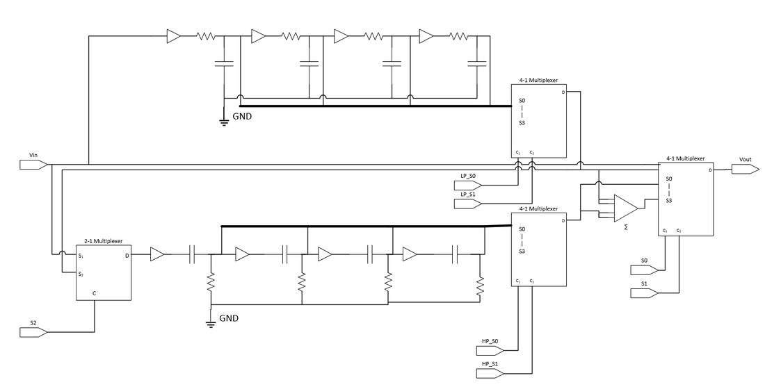
Figure 13: Filter Schematic
|
|
In Figure 13, is the schematic for how this module is built. On top is a regular RC low-pass filter duplicated four times with taps to change the order. The bottom is mimicked except with an RC high-pass filter network. All resistances in each network are controlled simultaneously by a programmable resistor array that specifies an amount from 1k to 100k ohms. These parameters were measured from the i2C programmable resistor being used and were implemented in the MATLAB model in the initial step. The input and output stages of the filters are routed using analog multiplexers to configure the signals in series or parallel to the final output. The multiplexers also control the feedthrough condition as well as regular low and high pass. Buffers are used throughout as a high input impedance stage separator so that you can tap into the filter in multiple places to change its order.
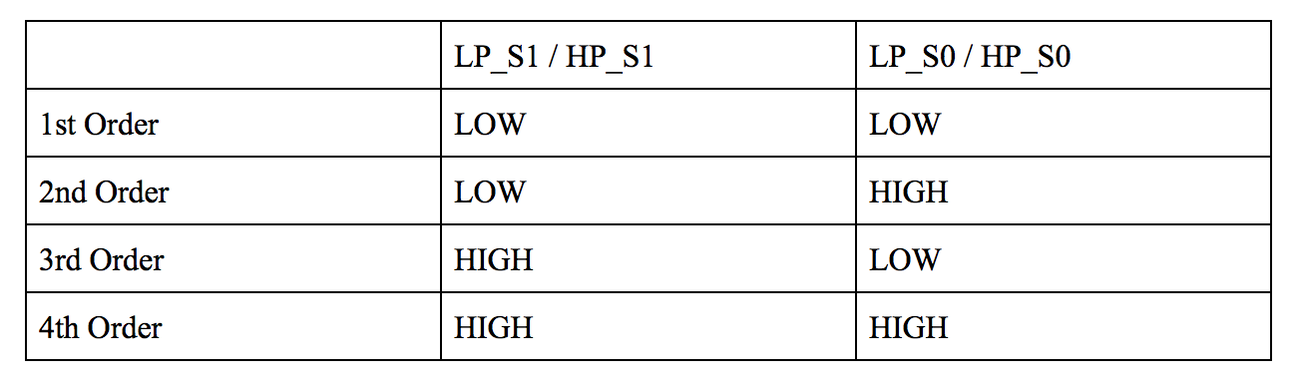
Table 1: Low-Pass and High-Pass order control signals
|
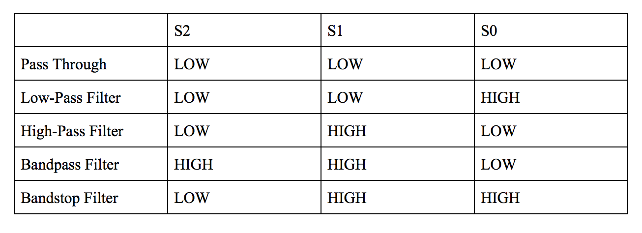
Table 2: Filter type control signals
|
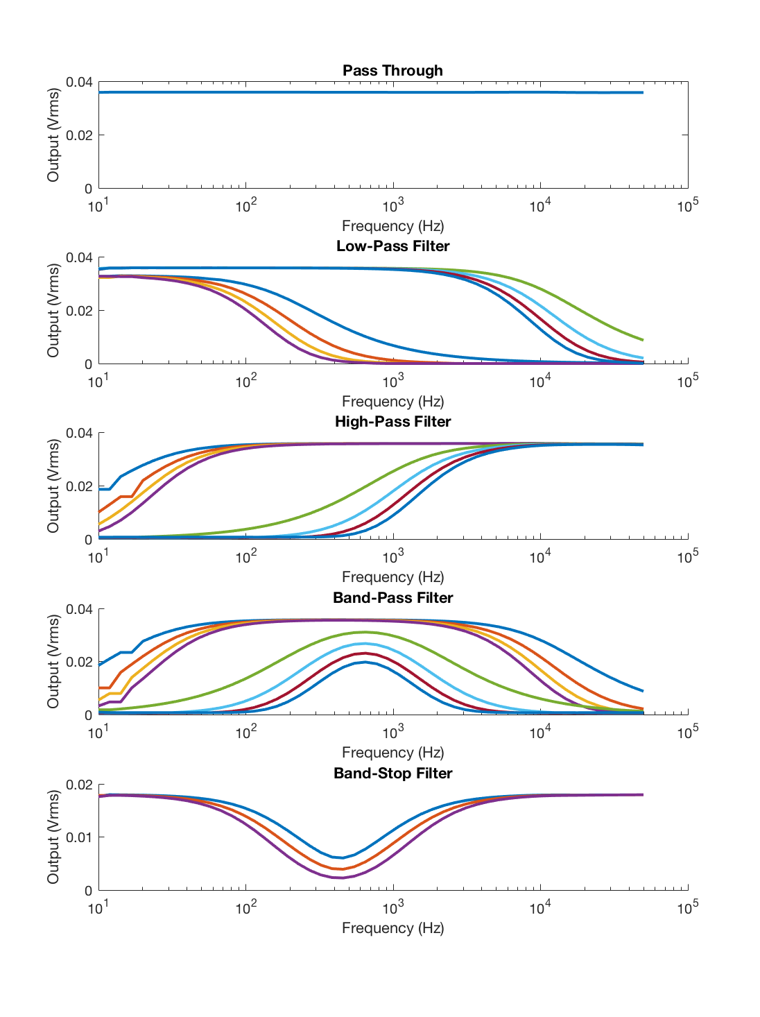
Figure 14: Collected data from a 100mVpp (35.3mVrms) sine wave swept from 10Hz to 50kHz.
Following construction of this circuit, a performance measure was obtained for the amplitude of the output signal as a function of frequency. This was done by sweeping an input sinusoid of amplitude 100 mVpp from 10 Hz to 50 kHz and recording the output signal. The final results are shown in Figure 14. During this process, the capacitor value was tuned to match the characteristics of the simulated MATLAB model (C_low-pass=0.01uF, C_high-pass=0.1uF).
Construction:
Housing
To handle all the components, the construction of a housing was required. The inspiration for the design came from the Minimoog synthesizer as it provided a simplified user interface. Initial drafts of the housing were developed in Autodesk Fusion modeling software with each piece constrained to 12inch thickness and dimensions tailored to golden ratio (1.618) multiples for physical appeal. After all the pieces were created, each individual section was imported into a master assembly to virtually put the device together ensuring proper fit, see Figure 15.
To handle all the components, the construction of a housing was required. The inspiration for the design came from the Minimoog synthesizer as it provided a simplified user interface. Initial drafts of the housing were developed in Autodesk Fusion modeling software with each piece constrained to 12inch thickness and dimensions tailored to golden ratio (1.618) multiples for physical appeal. After all the pieces were created, each individual section was imported into a master assembly to virtually put the device together ensuring proper fit, see Figure 15.
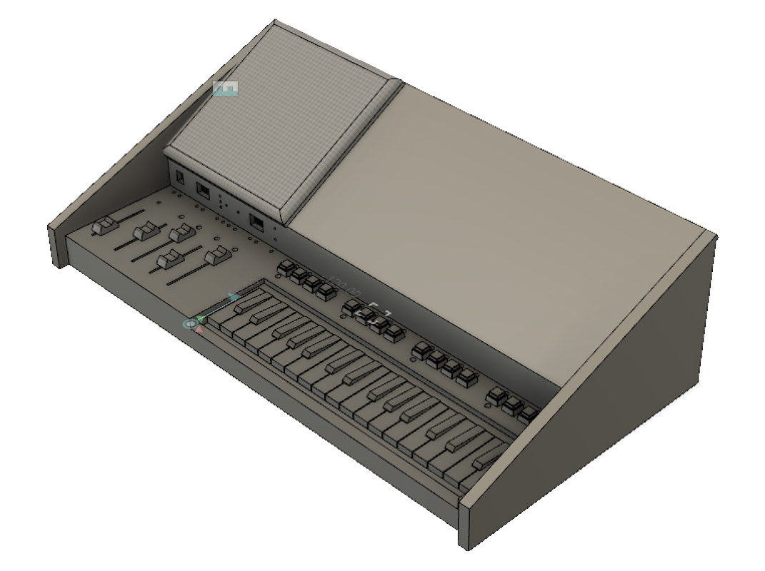
Figure 15: 3D Model Rendering
|
|
The wood I decided on using was Aspen and Poplar. It is relatively inexpensive and easier to work with (softwood) compared to Oak or Cherry. The downsides of working with Aspen and Poplar were that it split easily if a dull or careless cut was made, also it absorbs stain unevenly (preventable with a coat of primer). The boards purchased were sized 6' x 8" x 0.5" with some having to be glued together to form the wider sections. Cuts were made to the dimensions set in the technical drawings using a table saw, radial arm saw, bandsaw, and jointer. Assembling the wooden pieces were done by coating the joining surfaces with wood glue and fixing together with a clamp, followed by a nail gun. The top surface needed to open from the front and was attached at the back with hinges.
Following the assembly, all surfaces were sanded, primed and two coats of stain were applied. The color, "Sedona Red", was chosen to give it a Cherry finish look and prevent clashing between the wood with black components, see Figure 17. Two coats of satin varnish were added to seal the finish. On the top plane, speaker holes were created on the left side and hidden behind a speaker cover made of a frame wrapped in sound material. The speaker cover is fastened to the effect plane with neodymium magnets sunk into the frames perimeter as well as to the underside of the effect plane.
Following the assembly, all surfaces were sanded, primed and two coats of stain were applied. The color, "Sedona Red", was chosen to give it a Cherry finish look and prevent clashing between the wood with black components, see Figure 17. Two coats of satin varnish were added to seal the finish. On the top plane, speaker holes were created on the left side and hidden behind a speaker cover made of a frame wrapped in sound material. The speaker cover is fastened to the effect plane with neodymium magnets sunk into the frames perimeter as well as to the underside of the effect plane.
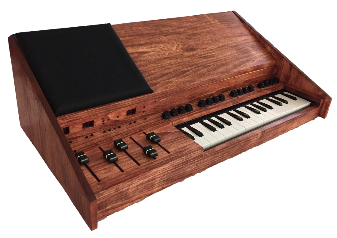
Figure 17: Synthesizer Case
|
|
Component Population
A number of buttons and knobs were required for the user to interface with the device. This is seen in Figure 17 where through-hole push buttons were used for the sequencer, sliders for the gain adjustments and tactile buttons for parameter configuration. For information, the display LED’s were used to illuminate corresponding holes as well as HEX displays for showing the mode of operation. All of the panel components were soldered onto perf board which was mounted to the case via standoffs and glue.
A number of buttons and knobs were required for the user to interface with the device. This is seen in Figure 17 where through-hole push buttons were used for the sequencer, sliders for the gain adjustments and tactile buttons for parameter configuration. For information, the display LED’s were used to illuminate corresponding holes as well as HEX displays for showing the mode of operation. All of the panel components were soldered onto perf board which was mounted to the case via standoffs and glue.
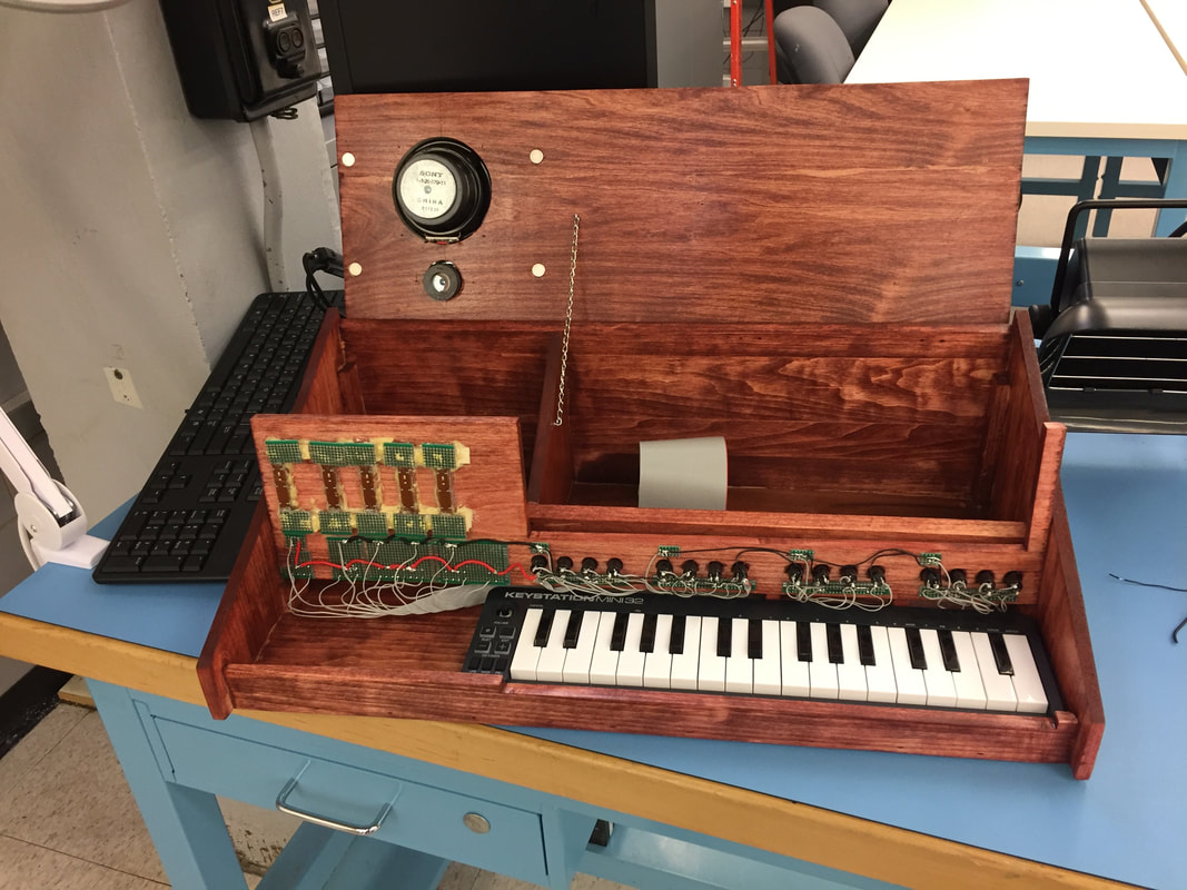
Figure 18: Front Panel Wiring
|
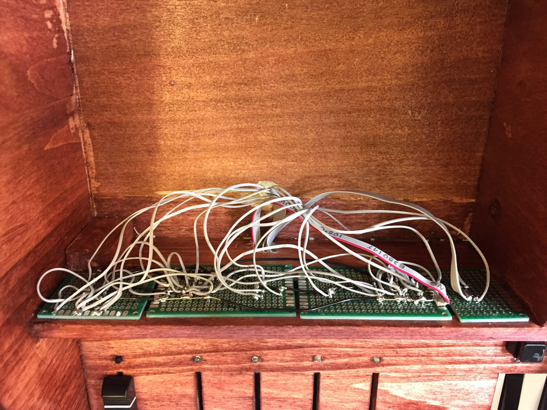
Figure 18: Display Wiring
|
In order to interface with all the mounted electronics, a great deal of input and output were required. Initially, the plan was to solder each connection directly to the PCB. However, after considering how cumbersome of a task this would become, a different approach was strategized. The result was to use ribbon cables with a female header that could be connected to the male receptacle located on the PCB. This allowed for ease in debugging and connection to the circuit as well as mitigation of problems with strain relief. Before wiring to the hardware began, a spreadsheet was created laying out the component connection order. Following this, the connections were wired chronologically to ensure the correct recipient was maintained. Power signals required a smaller gauge wire to prevent large voltage drops from occurring. In Figure 18, the underside of the panel wiring is shown.
PCB Creation
Initial circuits were prototyped on a breadboard. However, in order to fit all the circuits inside the housing, a PCB was needed to save space and eliminate potential wiring errors. The process for this development began by creating a schematic, shown in Figure 19, describing how all the hardware was connected. The schematic was sectioned off into five quadrants that grouped the hardware into distinct functions. For instance, the bottom left quadrant handles the sequencer whereas the one to the right is for generating signals, the top is the state machine logic for the user interface. Following that, validation was performed by printing out the schematic on a large sheet of paper and checking off each connection. This tedious step caught most of the errors before moving onto the layout. In layout, the schematic document is translated into a physical interpretation of the connections and hardware placement. Having an enormous amount of connections I decided to use the autoroute tool after placing the hardware. Finally, after passing design rule constraints the board was ordered. When received, it was filled with sockets and populated with components in their locations. The result is shown in the completed circuit board in Figure 19.
Initial circuits were prototyped on a breadboard. However, in order to fit all the circuits inside the housing, a PCB was needed to save space and eliminate potential wiring errors. The process for this development began by creating a schematic, shown in Figure 19, describing how all the hardware was connected. The schematic was sectioned off into five quadrants that grouped the hardware into distinct functions. For instance, the bottom left quadrant handles the sequencer whereas the one to the right is for generating signals, the top is the state machine logic for the user interface. Following that, validation was performed by printing out the schematic on a large sheet of paper and checking off each connection. This tedious step caught most of the errors before moving onto the layout. In layout, the schematic document is translated into a physical interpretation of the connections and hardware placement. Having an enormous amount of connections I decided to use the autoroute tool after placing the hardware. Finally, after passing design rule constraints the board was ordered. When received, it was filled with sockets and populated with components in their locations. The result is shown in the completed circuit board in Figure 19.
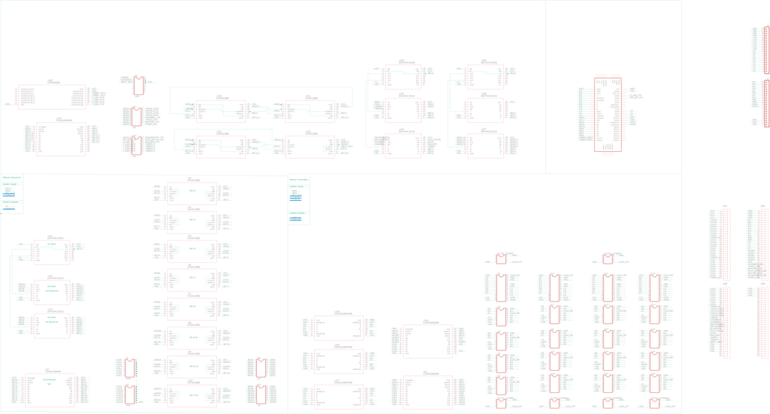
Figure 19: Generation Schematic
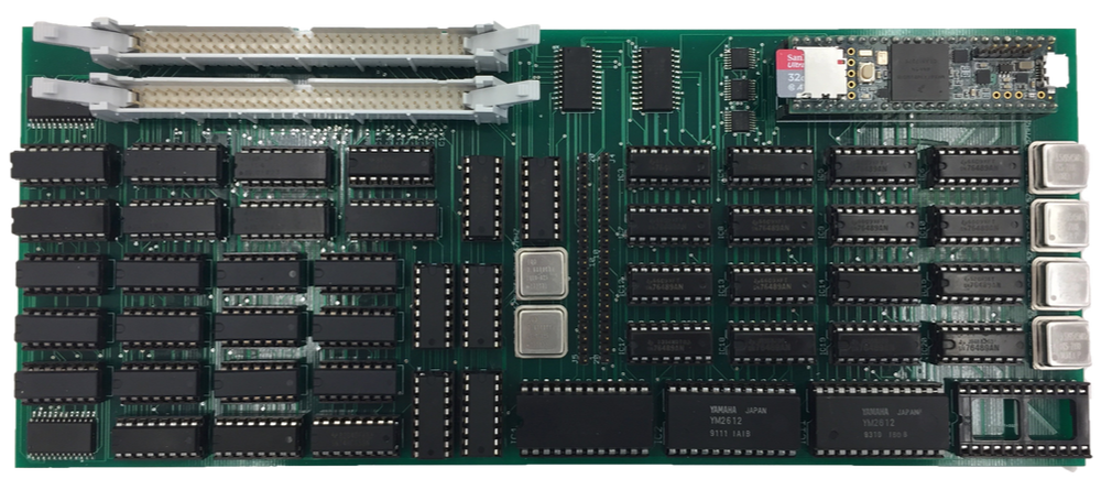
Figure 19: Generation PCB
On top of the Generation Board, in Figure 19, are the two 60 pin I/O ribbon cable ports below that is the state machine logic and on the right half of the board are the audio generation circuits. The middle of the board holds chips for reading and writing into the hardware such as multiplexers, decoders, and logic level converters. It also has 2 rows of header pins that allow the ability to access various IC output signals.
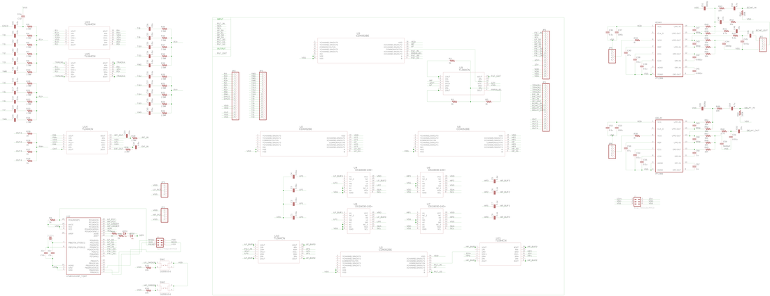
Figure 20: FX Schematic
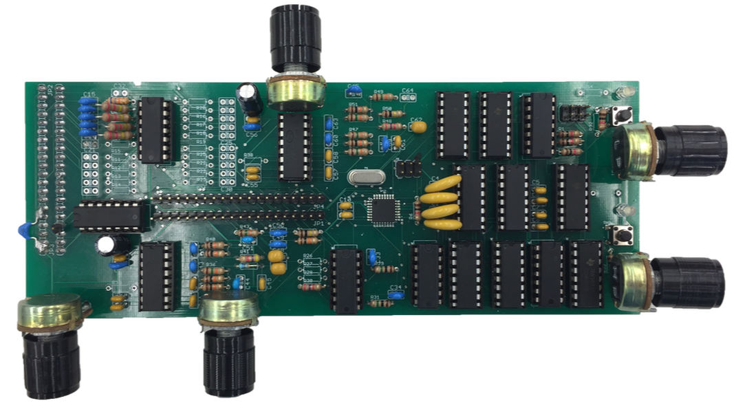
Figure 20: PCB
The second board created was the effects (FX) board used to manipulate the Generation Boards output signals. The process for developing this board was similar to the first by dividing up the schematic into sections to tackle each functionality. At the core of this board is the filter network that is controlled by its very own Atmega328p microcontroller. This provides the user freedom to change filter type, order, and cut off with minimal work. Alongside this are effects for distortion and time-based elements. The end product for the FX Board is shown above in Figure 20. This piece of hardware takes all the incoming signals and sums them together into their four-track nodes. After that, the user can use the 2 rows of headers in the middle of the board to jump signals into their desired effect. The knobs seen on the side of the board in Figure 20 are used to change parameters in the effects. For instance the two knobs on the right control the corner frequency of the high and low pass filter. After completing the desired signal chain the user can feed the output into a final summing amplifier to boost the gain for output to speakers.
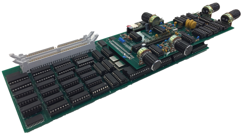
Figure 21: Generation and FX PCB Connection
In Figure 21 both boards are connected to show the normal operation. An isolation layer was added on top of the metal crystal oscillators to prevent shorting when the FX Board rested on top. In the future, version 2 of this board will have both the Generation and FX all on one master board. Some other changes for future board versions are to increase the thickness of the power traces to avoid a large drop in voltage across the board and add decoupling capacitors near the VDD and GND of the generation IC’s to prevent noise leakage onto the power lines which affected the state machine flip-flops.
Conclusion:
Completing hardware integration resulted in a working device that could generate polyphonic sounds using a variety of researched synthesis techniques. The device was also capable of applying desired effects to the output signals through a pluggable signal routing scheme. My initial goal for the project was to create an intuitive hybrid synthesizer that abstracted the user from internal complexities. In the end, I was able to accomplish this through hardware reuse which resulted in minimizing the number of buttons needed without reducing functionality. The final architecture of the device made it easy to incorporate many of the synthesis techniques into one system by treating each as a single module that would eventually sum together in a later stage. One of the most challenging aspects of this project was keeping the ideas constrained into something that was feasible within the six months span of this project. In the end, I was able to compromise on this by allowing the ability for ease of future additions. The building of this project allowed me to develop a more concrete understanding of how synthesizers evolved into what they are today and some of the various techniques available for complex signal generation. This project also gave me valuable exposure in completing beginning to end system designs of both hardware and software. It enabled me to use a wide breadth of what I learned throughout college to accomplish the project.
References:
[1] Nov, Y. (2004, January 24). Explaining the Equal Temperament. Retrieved August 28, 2018, from https://www.yuvalnov.org/temperament/
[2] Roland Australia. (2017, May 26). A Beginner's Guide to Subtractive Synthesis. Retrieved September 2, 2018, from https://www.rolandcorp.com.au/blog/beginners-guide-subtractive-synthesis
[3] Earl, D. (2013, November 01). A Brief history of FM Synthesis. Retrieved September 5, 2018, from https://ask.audio/articles/a-brief-history-of-fm-synthesis
[4] Dannenberg, R., & Oland, A. (2016, October 2). FM Synthesis. Retrieved September 5, 2018, from http://www.cs.cmu.edu/~music/icm-online/readings/fm-synthesis/fm_synthesis.pdf
[5] Sega Genesis Technical Manual - YM2612 section. (n.d.). Retrieved September 1, 2018, from http://www.smspower.org/maxim/Documents/YM2612
[6] ADSR envelope. (2014, August 19). Retrieved August 11, 2018, from https://libremusicproduction.com/answer/adsr-envelope
[7] CHOWNING, J. (1977). The Synthesis of Complex Audio Spectra by Means of Frequency Modulation. Computer Music Journal,1(2), 46-54. Retrieved from http://www.jstor.org/stable/23320142
[8] Smith, J. O. (2011). Spectral audio signal processing. Stanford, CA: W3K Publishing.
Comment Box is loading comments...
