Enigma Simulator
The Enigma Machine is a mechanical cypher machine that takes a user input from keyboard and outputs the corresponding character with a light. What makes this device unique is there is not a direct mapping between characters. For example a T does not always output the character W, so a TT may output as WU. The machine is comprised of 3 rotors that have 26 different inputs and outputs. The number 26 because there are 26 letters in the english alphabet. Each rotor has a distinct wiring with each input wired to a single output. An example of the rotors I generated are shown below.
The Enigma Machine is a mechanical cypher machine that takes a user input from keyboard and outputs the corresponding character with a light. What makes this device unique is there is not a direct mapping between characters. For example a T does not always output the character W, so a TT may output as WU. The machine is comprised of 3 rotors that have 26 different inputs and outputs. The number 26 because there are 26 letters in the english alphabet. Each rotor has a distinct wiring with each input wired to a single output. An example of the rotors I generated are shown below.

Rotor 1

Rotor 2

Rotor 3
The rotor pictures above show the input on the top row and output on the bottom row. The wiring is represented as being wired where letters match. After each input the system will rotate the rotors like a clock. Rotor 1 will rotate one position every input. Rotor 2 will rotate once every time rotor 1 completes a full rotation. Rotor 3 will rotate once every time rotor 2 completes a full rotation. You may relate it to thinking of a clock where rotor 1= seconds, rotor 2=mins, rotor 3=hours. A reflector takes the output signal for rotor 3 and rewires it into the system to go back through the rotors.
The data path is as follows:
Input -> Rotor 1 -> Rotor 2 -> Rotor 3 -> Reflector -> Rotor 3 -> Rotor 2 -> Rotor 1 -> Output
The data path is as follows:
Input -> Rotor 1 -> Rotor 2 -> Rotor 3 -> Reflector -> Rotor 3 -> Rotor 2 -> Rotor 1 -> Output

Reflector
The reflector pictured above shows the reflection wiring. The top and bottom letters represent the reflection wiring. For instance OU in position 1 is fed into UO in position 6. The reflector does not rotate.
In the implementation I built there are 17,576 different combinations that can be made. This is because there are 3 rotors with 26 different positions to choose from. 26 x 26 x 26=17,576. To get even more secure the device had the feature of adding a plugboard which affected the input and output signal. The plugboard has 10 plug wires that connect two letters into a pair to swap the letters. The plugboard does not change the input plugs during the Encrypting or Decrypting process. This added level of security creates 2.6493759e+18 different combinations. 26!/(10!*6!*2^10)=150,738,274,937,250. 26!=the number of different arrangements of alphabetical letters. 10!= not worrying about order of the plugs. 6!=(26-10*2)! only need 10 pairs. 2^10=number of different ways to plug the 10 plug wires in.
150,738,274,937,250*17,576=2.6493759e+18 different combinations with the added plugboard.
The data path including the plugboard is as follows:
Input -> Plugboard -> Rotor 1 -> Rotor 2 -> Rotor 3 -> Reflector -> Rotor 3 -> Rotor 2 -> Rotor 1 -> Plugboard -> Output
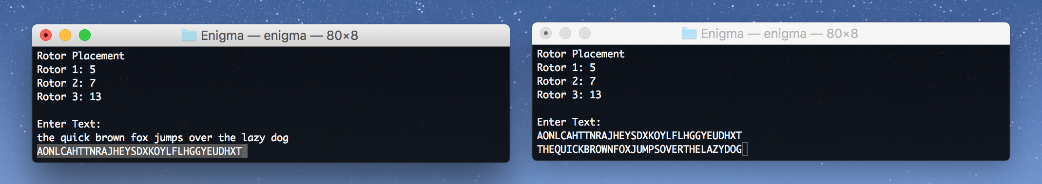
Encrypt/Decrypt Example
JavaScript Simulator
|
|
|
Widget is loading comments...
